8
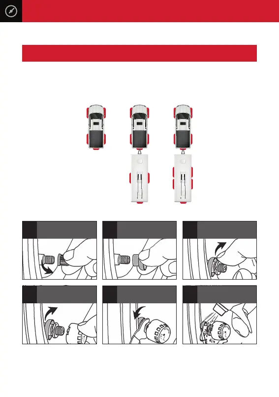
Each sensor has been marked with a position number and has been paired to the
monitor from factory. Please install the sensors according to the below diagram.
Wheel
Sensor
Location
3. SENSOR INSTALLATION
1
Unscrew the valve cap
3
Screw on the nut
5
Tighten up the nut to the
sensor with the spanner
2
Insert dust proof cover onto
the valve stem
4
Screw on the sensor
6
Check air leakage by
spraying soapy water
2
4
6
5
8
1
3
7
IC008
2
4
7
9
10
1
3
6
8
IC010
5
IC005
2
4
5
1
3
5
Please Note: Use of the lock nuts and rubber dust covers is optional. Non use will
not aect performance or warranty of your product.