ELECTRICAL SHOCK HAZARD!
Turn o power at the main service
panel by removing the fuse or switching the appropriate circuit
breaker to the OFF position before working on a high voltage control.
Installation of the ICM550 shall be performed by trained
technicians only. Adhere to all local and national electric codes.
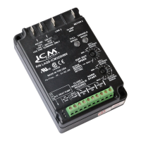
Never turn the dial backward, always turn the dial
clockwise to adjust. Do not attempt to touch or adjust the hands of the
clock as this may cause permanent damage to the clock.
The following example shows the clock
set to 2:30 PM.
Turn the outer dial clockwise until the
inner clock hands point to the correct
time. Each tick mark on the outer dial
represents 15 minutes.
The inner dial is representative of
conventional clock, with the printed
“hand” showing the hour and the physical
hand showing the minute. The time displayed on
the inner dial will always correspond with the time on the outer dial.
Determine the appropriate cycle time
for your application. Next, set the
switches for each 15 minute interval
you require by moving the switch to
the outer position.
Each switch represents a 15 minute
interval and there are 4 intervals per
hour.
In this example, the system will begin one
timed cycle at 5:00 PM, which will last for 45
minutes (3 intervals). The unit will resume normal operation at 5:45 PM.
If multiple cycles are required, please select the appropriate DIP
switches to represent each 15 minute interval throughout the 24 hour
period where desired.
INSTALLATION, OPERATION & APPLICATION GUIDE
For more information on our complete range of American-made products – plus wiring
diagrams, troubleshooting tips and more, visit us at www.icmcontrols.com
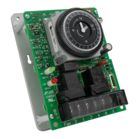
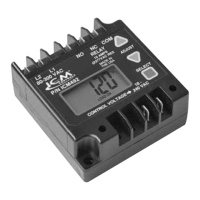
ICM550
Multi-Functional Timer
Inputs:
• Nominal voltage range: 120-240 VAC
• Frequency: 60 Hz
Outputs:
• Type: Relay
Contact Ratings:
• Compressor: [2]&[4]: 30A R, 1 HP @ 120 VAC, 2 HP @ 240 VAC
• Electric heat: [1]&[3]: 40A R, 1 HP @ 120 VAC, 2 HP @ 240 VAC
• Fan: [1]&[F]: 30A R, 1 HP @ 120 VAC, 2 HP @ 240 VAC
Environmental
• Operating temperature: -40 to +131°F
• Operating humidity: 0-95%, non-condensing
Mechanical
• Construction: Open board (plastic bracket mounted).
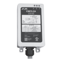
The ICM550-ENC comes packaged in a NEMA Type 4X rated
weatherproof enclosure
• Mounting: Vertical or horizontal orientation
Timing
• Minimum cycle time: 15 minutes
• Maximum cycle time: 23 hours 45 minutes
• Terminate cycle: Cycle can be terminated by shorting “X to N”
Status LED
• Cycle mode: (Red LED)
• Normal mode: (Green LED)
• Grasslin: 010-0011B, DT040, DT140, DTAV40, DTMV, DTSX
• Paragon: 8041, 8045, 8047, 8141, 8143, 8145, 8245, 8247
• Precision: 6041, 6045, 6047, 6141, 6145
ICM550 control module, bracket mount, installation guide, terminal
block & wiring diagram label sheet, sheet metal screws
hex head screws .
• Commercial defrost timer
• Pool & spa circulation pumps
“USE COPPER WIRES ONLY”
Tightening torque 15 in-lb.
SPECIFICATIONS
REPLACES
PACKAGE CONTENTS
APPLICATIONS
TERMINAL BLOCK SAMPLE WIRING DIAGRAM (FOR DEFROST APPLICATION)
TO SET THE CURRENT TIME
TO SET DEFROST TIME
LISTED
US
U
L
®
C
Compressor
Contactor Coil
Solenoid Valve
Switch Position
Mode A
Defrost
Thermostat
with Fan Delay
Fan
T-Stat
K1
F N X
K2
Defrost
Heater
120
VAC