Table 1 – Mode Switch Selection Table
Grasslin SW1
DT040 A
DT140 A
DTMV A
DTSX A
DTAV40 A/B per system
Time Initiated &
Time Terminated
Paragon Precision SW1
8045 6045 A
8041 6041 A
8047 6047 B
Time Initiated &
Pressure Terminated
Paragon Precision
8245 A
8247 B
Time Initiated & Pressure or
Temperature Terminated
Paragon Precision SW1
8145 6145 A
8141 6141 A
8143 B
Refrigeration Mode: Green light ON and Red light OFF
(K1 NC, K2 NC)
Defrost Mode: Red light ON and Green light OFF
(K1 NO, K2 NO)
Mode “A” Operation
Refrigeration Mode: Red and Green lights OFF
(K1 NC, K2 NO)
Defrost Mode: Red and Green lights ON
(K1 NO, K2 NC)
Mode “B” Operation
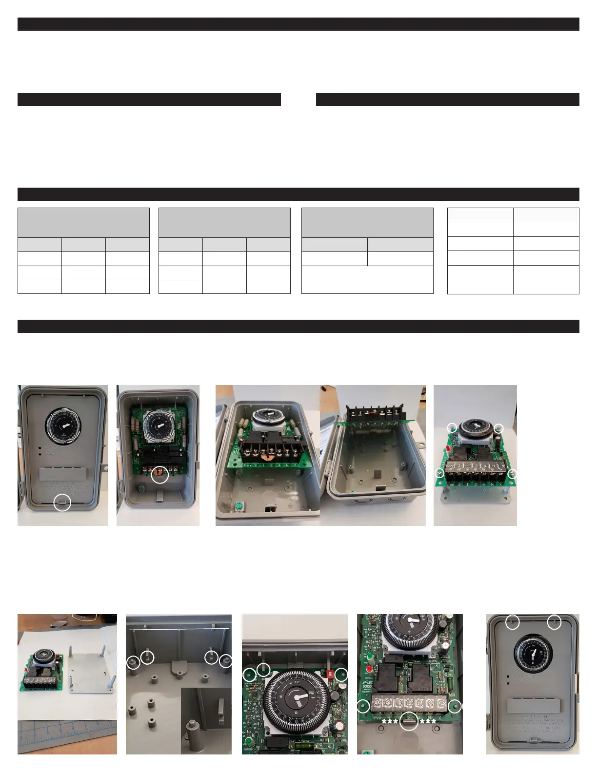
Bracket removed from
ICM550. Discard the bracket
and screws.
B
A
The ICM550 correctly
placed in channels (A) with
screw holes secured using
the four plastic standoffs (B)
of the enclosure.
B
Firmly press the board down
with thumbs on both sides
“***” of “C”.
B B
C
A A
B
A
B
A
B
D-ChannelD-Channel
Replace the cover by
aligning the top of the
cover into channel “D”
then press the bottom of
the cover down rmly until
it snaps into place.
B
B
Push plastic tab DOWN
to release the cover and
pull the cover out of the
enclosure.
Push plastic tab DOWN to
release the board.
Pull the bottom of the existing board UP until the board is
detached from the enclosure.
Remove the four screws (circled) to
release the ICM550 from its bracket. The
four holes will be used to connect the
ICM550 to the Grasslin enclosure.
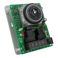
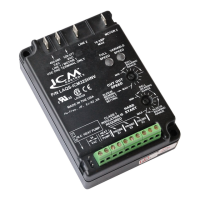
Installing the ICM550 into a Grasslin Enclosure
The Mode selection switch is used to set up the condition of relay K2 based on the model you are replacing (See Table 1). When
set up in Position A, relay K2 is normally closed and will open in defrost. When set up in position B, relay K2 is normally open and
will close in defrost.
Mode Selection Switch
Align the ICM550 so it slides
UP and INTO the plastic
channels (A), while ensuring
the screw holes on the
ICM550 line up with the plastic
standoffs (B) on the enclosure
CCC
D D