Do you have a question about the Icom HM-162B/SW and is the answer not in the manual?
Instructions for selecting Channel 16 on the radio.
Procedure to select and program the call channel.
Steps to tune into and select available weather channels.
How to switch between USA, International, and Canadian channel groups.
How to enable the standard key lock feature.
Procedure for activating the all-key lock for complete lockout.
How to use the beep function for intercom communication.
Procedure to access and navigate the device's set mode menu.
Procedure for sending a basic distress alert.
Steps to transmit a distress call with specific nature details.
How to send a DSC call to a specific vessel.
Procedure to reply to an individual DSC call.
Steps to send a DSC call to multiple vessels.
How to broadcast a DSC call to all vessels in range.
Procedure to request position data from another vessel.
How to respond to a position request with your data.
Steps to send a DSC position report to a specific vessel.
How to add or edit DSC address book entries.
Procedure to remove entries from the DSC address book.
Setting the local time offset from UTC for DSC operations.
Verifying the device's own MMSI (DSC self ID) code.
Enabling or disabling automatic responses to DSC calls.
Configuring the output of position data to external equipment.
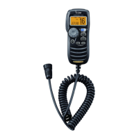
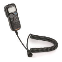
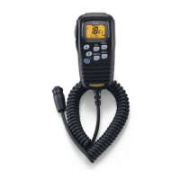
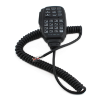
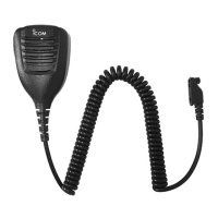
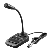
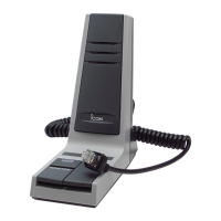
The Icom HM-162B/SW is a remote-control microphone designed for use with the IC-M604 transceiver, or similar compatible devices. It extends the control and communication capabilities of the main unit, offering a range of functions for marine radio operation and an optional intercom feature.
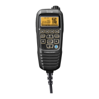
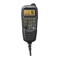
The HM-162B/SW provides comprehensive control over the connected transceiver, allowing users to manage various settings and operations directly from the microphone.
The microphone features a clear display with several indicators:
| Brand | Icom |
|---|---|
| Model | HM-162B/SW |
| Category | Microphone |
| Language | English |