EasyManua.ls Logo

Icom HM-162B User Manual

Icom HM-162B
8 pages
To Next Page IconTo Next Page
Page #1 background imageLoading...
Page #1 background image
INSTRUCTIONS
REMOTE-CONTROL MICROPHONE
HM-162B/SW
Thank you for purchasing the HM-162B/SW
REMOTE
-
CONTROL MICROPHONE
. The COMMANDMIC III
TM
is a
remote control microphone for use with the IC-M604
or else.
Please read the connected transceiver’s instruction
manual carefully before installation and operation.
These instructions are just described the remote-
control operations only.
q BUSY/TRANSMIT INDICATOR
BBUUSSYY
” appears when receiving a signal or when the
squelch opens.
TTXX
” appears while transmitting.
w RECEIVER ATTENUATOR INDICATOR
LLOOCC
” appears when the Attenuator function is in use.
e SCRAMBLER INDICATOR
SSCCRRAAMM
” appears when an optional voice scrambler is acti-
vated.
r SCAN INDICATOR
Either “
NNOORRMMAALL SSCCAANN
” or “
PPRRII--SSCCAANN 1166
” scan type
appears while scanning.
DDUUAALL 1166
” appears during dualwatch; “
TTRRII 1166
” ap-
pears during tri-watch.
t SELECTOR STATUS INDICATOR
Indicates the [SELECTOR] active status;
[[VVOOLL]]
” appears when [SELECTOR] as the audio volume.
[[SSQQLL]]
” appears when [SELECTOR] as the noise squelch
controller.
[[CCHH ]]
” appears when [SELECTOR] as the channel selector.
y POSITION INDICATOR
Shows the GPS position data.
•“
????
” may blink every 2 sec. instead of position data when
the GPS position data is invalid. In this case, the last position
data is held for up to 23.5 hours.
•“
????
” may blink every 2 sec. instead of position data 4 hours
after the position data is input manually, up until 23.5 hours
have past.
NNoo PPoossiittiioonn
” appears when no GPS receiver is con-
nected and no position data is input manually.
u TIME ZONE INDICATOR
LLooccaall
” appears when the offset time data in the ‘Set
up’ menu is entered.
NNoo TTiimmee
” appears when no GPS receiver is connected
and no time data is input manually.
i CHANNEL COMMENT INDICATOR
Channel comment appears, if programmed.
o CHANNEL NUMBER READOUT
Indicates the selected operating channel number.
!0 KEY LOCK INDICATOR
Appears while the Key Lock function is in use.
Blinks while the All Key Lock function is in use.
!1 LOW BATTERY INDICATOR
“” blinks when the battery voltage drops to approx. 10 V
DC or below.
!2 CALL CHANNEL INDICATOR
CCAALLLL
” appears when the call channel is selected.
AALLEERRTT
” appears when the Weather Alert function is in
use; blinks when an alert tone is received.
!3 CHANNEL GROUP INDICATOR
Indicates whether an International “
IINNTT
,” U.S.A. “
UUSSAA
,”
Canadian “
CCAANN
” or weather “
WWXX
” channel is selected.
!4 DUPLEX INDICATOR
Appears when a duplex channel is selected.
Duplex channel has a different TX and RX frequency.
!5 TAG CHANNEL INDICATOR
Appears when a tag channel is selected.
!6 POWER INDICATOR
2255WW
” appears when high power is selected.
11WW
” appears when low power is selected.
!7 RX SPEAKER INDICATOR
Appears when an RX speaker function is activated.
BUSYBUSY-25W25W------INTINT------CALLCALL
LOCLOC- -- -- DUPDUP
SCRAMSCRAM--TAGTAG
NORMALNORMAL-SCANSCAN
-3434°34.506N34.506N
123123°23.236W23.236W
LocalLocal----1:101:10- - CALLINGCALLING
RXRX
[VOL]
w
q
e
y
u
r
t
!6!7 !4!5 !3 !2
o
!0
!1
i
Accessories included with the HM-162B/SW: Qty.
q Connection cable (OPC-1540*: 6 m; 20 ft) ....................... 1
w Mounting base .................................................................. 1
e Connector cap .................................................................. 1
r Microphone hanger .......................................................... 1
t Screws (M3 × 16; tapping) ............................................... 5
*: OPC 1540 has external speaker leads as illustrated at right.
(Yellow: Audio, Black: Speaker ground)
These instructions are described when the HM-162 is connected to the IC-M604. Some operations or indications may be dif-
ferent as these instructions depending on the connecting transceiver.
x Function display
z HM-162B/SW supplied accessories
qwe
r
t
Yellow
Black
1
Question and Answer IconNeed help?

Do you have a question about the Icom HM-162B and is the answer not in the manual?

Icom HM-162B Specifications

General IconGeneral
Connector8-pin modular
PTT SwitchYes
TypeDynamic
Impedance600 ohms
Frequency Response300 Hz - 3000 Hz

Summary

HM-162B/SW Supplied Accessories

Function Display Indicators

Key Operational Status Indicators

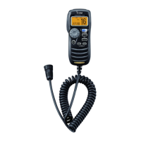
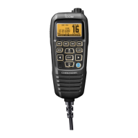
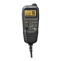
Indicates transmission, reception, squelch, and power status for immediate operational feedback.

Information and Mode Indicators

Displays GPS data, time, channel selection, lock status, and battery alerts for comprehensive monitoring.

Panel Description and Key Functions

Core Control Keys

Essential keys for transmission, selection, confirmation, and mode adjustment like PTT, Selector, Enter, and Volume.

Channel and Scan Control Keys

Buttons for channel selection, scanning modes (Scan, Dualwatch, Tri-watch), and specific channels like 16/Call.

Special Function Keys

Keys for initiating distress calls, adjusting power, accessing menus, and activating intercom or hailer functions.

Selector Dial Functionality

Dynamic Selector Dial Actions

Explains how the Selector Dial's function changes based on other key presses and its default return behavior.

Channel Selection Procedures

Selecting Specific Channel Groups

Guides through selecting Channel 16, Call Channel, Weather, and regional channels (USA, INT, CAN).

Receiving and Transmitting Operations

Basic Transmit and Receive Steps

Covers powering on, adjusting audio/squelch, selecting power, and using the PTT for communication.

Attenuator and Power Settings

Details on using the Attenuator for signal reception and selecting transmit power levels.

Monitor Function

Activating and Deactivating Monitor

Explains how to enable and disable the monitor function for immediate audio feedback.

Specialized Operating Modes

Hailer and RX Speaker Functions

Guides on using the hailer for announcements and the RX speaker for external audio output.

Intercom and Foghorn Features

Details on using the intercom for communication and the automatic foghorn for alerts.

Display Backlight Adjustment

Backlight Level Control

Describes how to adjust the display and key backlight brightness for optimal visibility.

Advanced Setting and Programming

Set Mode Configuration

Explains how to enter Set mode to configure transceiver and microphone functions like scan type and contrast.

Channel Comment Programming

Details on how to label memory channels with custom alphanumeric IDs for easier identification.

DSC Menu and Operation

Guides on navigating the DSC menu for various functions like position input, individual calls, and group calls.

Distress Call Procedures

Simple and Regular Distress Calls

Provides step-by-step instructions for initiating distress calls, including position and time data input.

Transmitting DSC Calls

Individual and Group Call Transmission

Details on sending individual calls, acknowledgments, group calls, and all-ships calls via DSC.

Position Request and Report Calls

Guides on requesting and reporting position information using DSC, including reply procedures.

Received Messages and DSC Setup

Managing Received DSC Messages

Explains how to access and manage distress and other messages stored by the transceiver.

DSC Set Mode Configuration Options

Covers programming individual/group IDs, checking MMSI code, automatic acknowledgments, and NMEA output.
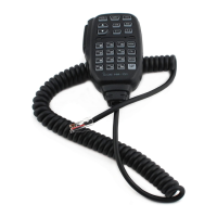
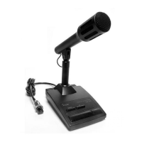
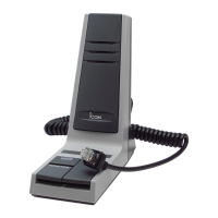
Related product manuals