INSTRUCTIONS
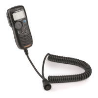
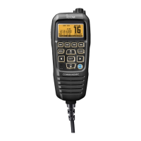
REMOTE-CONTROL MICROPHONE
HM-162E
Thank you for purchasing the HM-162E
REMOTE
-
CONTROL MICROPHONE
. The COMMANDMIC III
TM
is a
remote control microphone for use with the IC-M603
or else.
Please read the connected transceiver’s instruction
manual carefully before installation and operation.
These instructions are just described the remote-
control operations only.
q BUSY/TRANSMIT INDICATOR
➥ “
BBUUSSYY
” appears when receiving a signal or when the
squelch opens.
➥ “
TTXX
” appears while transmitting.
w RX SPEAKER INDICATOR
Appears during the RX speaker mode.
e SCRAMBLER INDICATOR
“
SSCCRRAAMM
” appears when an optional voice scrambler is acti-
vated.
r SCAN INDICATOR
➥ “
PPRRII--SSCCAANN 1166
” appears during Priority scan; “
NNOORR--
MMAALL SSCCAANN
” appears during Normal scan.
➥ “
DDUUAALL 1166
” appears during dualwatch; “
TTRRII 1166
” ap-
pears during tri-watch.
t SELECTOR STATUS INDICATOR
Indicates the [SELECTOR] active status;
“
[[VVOOLL]]
” appears when [SELECTOR] functions as the
audio volume.
“
[[SSQQLL]]
” appears when [SELECTOR] functions as the
noise squelch controller.
“
[[DDIIAALL]]
” appears when [SELECTOR] functions as the
channel selector.
y POSITION INDICATOR
➥ Shows the GPS position data.
•“
????
” may blink every 2 sec. instead of position data when
the GPS position data is invalid. In this case, the last position
data is held for up to 23.5 hours.
•“
????
” may blink every 2 sec. instead of position data 4 hours
after the position data is input manually, up until 23.5 hours
have past.
➥ “
NNoo PPoossiittiioonn
” appears when no GPS receiver is con-
nected and no position data is input manually.
u TIME ZONE INDICATOR
➥ “
LLooccaall
” appears when the offset time data in the ‘Set
up’ menu is entered.
➥ “
NNoo TTiimmee
” appears when no GPS receiver is connected
and no time data is input manually.
i CHANNEL COMMENT INDICATOR
Channel comment appears, if programmed.
o CHANNEL NUMBER READOUT
Indicates the selected operating channel number.
!0 KEY LOCK INDICATOR
➥ Appears while the Key Lock function is in use.
➥ Blinks while the All Key Lock function is in use.
!1 LOW BATTERY INDICATOR
“” blinks when the battery voltage drops to approx. 10 V
DC or below.
!2 CALL CHANNEL INDICATOR
“
CCAALLLL
” appears when the call channel is selected.
!3 CHANNEL GROUP INDICATOR
Indicates whether an International “
IINNTT
,” U.S.A. “
UUSSAA
,”
DSC “
DDSSCC
” or ATIS “
AATTIISS
” channel is selected.
• Depending on the connected transceiver’s version.
!4 DUPLEX INDICATOR
Appears when a duplex channel is selected.
• Duplex channel has a different TX and RX frequency.
!5 TAG CHANNEL INDICATOR
Appears when a tag channel is selected.
!6 POWER INDICATOR
➥ “
2255WW
” appears when high power is selected.
➥ “
11WW
” appears when low power is selected.
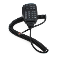
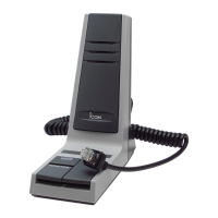
Accessories included with the HM-162E: Qty.
q Connection cable (OPC-1540*: 6 m; 20 ft) ....................... 1
w Mounting base .................................................................. 1
e Connector cap .................................................................. 1
r Microphone hanger .......................................................... 1
t Screws (M3 × 16; tapping) ............................................... 5
*: OPC 1540 has external speaker leads as illustrated at right.
(Yellow: Audio, Black: Speaker ground)
Icom, Icom Inc. and the logo are registered trademarks of Icom Incorporated (Japan) in the United States, the United Kingdom, Germany, France, Spain, Rus-
sia and/or other countries. COMMANDMIC III is a trademark of Icom Incorporated (Japan) in the United states.
These instructions are described when the HM-162E is connected to the IC-M603. Some operations or indications may be dif-
ferent as these instructions depending on the connecting transceiver.
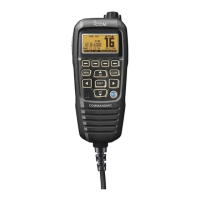
x Function display
z HM-162E supplied accessories