EasyManua.ls Logo

Icom HM-195 series - User Manual

Icom HM-195 series
8 pages
Print Icon
To Next Page IconTo Next Page
Loading...
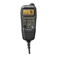
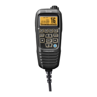
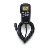
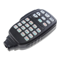
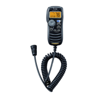
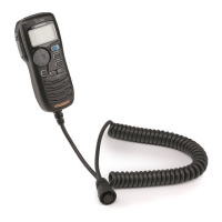
REMOTE-CONTROL MICROPHONE
INSTRUCTIONS q
HM-195 series
Thank you for choosing this Icom product. READ ALL IN-
STRUCTIONS carefully and completely before using this prod-
uct. These instructions describe only the remote-control opera-
tions. In this INSTRUCTIONS, the IC-M423/IC-M424 series is
used for an example. Some functions may not be usable, and
some screen, function name, and softkey name may be differ
-
ent, depending on the transceiver. See the transceiver’s manual
for detail operation.
Accessories included with the HM-195: Qty.
q Connection cable (OPC-1540*: 6 m; 20 ft) ....................... 1
w Mounting base ................................................................. 1
e Connector cap ................................................................. 1
r Microphone hanger .......................................................... 1
t Screws (M3 × 16 mm; self-tapping) ................................. 5
* The OPC-1540 has external speaker leads, as illustrated to the right.
(Yellow: Speaker (+), Black: Speaker (–))
z Supplied accessories
qw
e
r
t
Yellow
Black
!9
!5
!7
!8
!6
qw ietr!0you
!2
!3
!4
!1
q BUSY/TRANSMIT ICON (See n)
appears when receiving a signal or when the
squelch is open.
appears while transmitting.
w POWER ICON (See n)
“25W” appears when high power is selected.
“1W” appears when low power is selected.
e RX SPEAKER ICON (See ¤8)
Appears while in the RX Speaker mode.
r CHANNEL GROUP ICON (See b)
Selected channel group icons, USA “USA,” International
“INT,” Canadian “CAN,” ATIS “ATIS” or DSC “DSC” ap-
pears, depending on the transceiver version.
“WX” appears when the weather channel is selected.*
*For only USA and Australian version.
t CALL CHANNEL ICON (See b)
Appears when the Call channel is selected.
y DUPLEX ICON (See b)
Appears when a duplex channel is selected.
u FAVORITE CHANNEL ICON (See ⁄3)
Appears when a Favorite (TAG) channel is selected.
i MAIL ICON (See ¤4)
Blinks when there is an unread message.
o GPS ICON
Stays ON when the GPS receiver is activated and valid
position data is received.
Blinks when invalid position data is being received.
!0 SWITCH ICON (See ¤6)
Appears when the “CH AUTO SWITCH” or “CH 16 SWITCH”
in DSC Settings is set to ‘OFF.
!1 RT (Radio Telephone) ICON (See ‹4)
(For only USA version)
Appears while receiving or transmitting a signal, and when
the channel is changed.
!2 LOW BATTERY ICON
Blinks when the battery voltage drops to approximately 10 V
DC or less.
!3 CHANNEL NUMBER READOUT
Shows the selected operating channel number.
!4 CHANNEL NAME FIELD
The channel name appears, if entered. (See ,)
!5 KEY ICONS (See v)
Shows the assigned function of the softkeys on the front panel.
!6 TIME ZONE INDICATOR
Shows the current time when a GPS receiver is connect-
ed, or the time is manually entered.
When the GPS current time is invalid, “??” will blink every
2 seconds instead of the current time. After 23.5 hours has
passed, “NO TIME” will appear.
“??” will blink every 2 seconds instead of the current time, after
3 hours and 59 minutes have passed from when the time was
manually entered. The manually entered time is held for only
23.5 hours, and after that, “NO TIME” will appear.
“LOCAL appears when the offset time is set.
“MNL appears when
the time is manually entered
.
“UTC” appears when
the GGA, GLL or GNS GPS sen-
tence format is included in the GPS signal.
The date information appears when
the RMC GPS sen-
tence format is included in the GPS signal.
“NO TIME” appears when no GPS receiver is connected,
and no time is manually entered.
!7 POSITION INDICATOR
Shows the current position when a GPS receiver is con-
nected, or the position is manually entered.
When the GPS position is invalid, “??” may blink every 2
seconds instead of position. The last position is held for only
23.5 hours, and after that, “NO POSITION” will appear.
“??” will blink every 2 seconds instead of position, after 3 hours
and 59 minutes have passed from the time when the position
is manually entered. The manually entered position is held for
only 23.5 hours, and after that, “NO POSITION” will appear.
“NO POSITION” appears when no GPS receiver is con-
nected, and no position is manually entered.
!8 SCAN INDICATOR
“SCAN 16” appears during a Priority scan; “SCAN” ap-
pears during a Normal scan. (See ⁄4)
“DUAL 16” appears during Dualwatch; “TRI 16” appears
during Tri-watch. (See ⁄5)
!9 LOCAL ICON (See n) (
For only USA and Australian version.)
Appears when the Attenuator function is turned ON.
x Function display
The HM-195 remotely controls the transceiver and provides an
Intercom function.
q DISTRESS KEY [DISTRESS] (See ⁄9)
Hold down for 3 seconds to transmit a Distress call.
w PTT SWITCH [PTT]
Hold down to transmit, release to receive. (See n)
e MENU KEY [MENU]
(
See ‹1
)
Push to enter or exit the Menu screen.
r LEFT AND RIGHT KEYS []/[]
Push to switch to the previous or next key function that is
assigned to the softkeys. (See v)
Push to select the character or number in the table while
in the channel name, position entry mode, and so on.
(See ,, ⁄6, ⁄7)
t ENTER KEY [ENT] (See ,, ⁄0, ⁄6)
Push to set the entered data, selected item, and so on.
y
UP AND DOWN/CHANNEL SELECT KEYS [•CH]/[•CH]
Push to select the operating channels, Menu items, Menu
settings, and so on. (See b, ‹1)
Push to check Favorite channels, change the scanning di-
rection or manually resume a scan. (
See ⁄4
)
u CHANNEL 16/CALL CHANNEL KEY [16/C]
Push to select Channel 16. (See b)
Hold down for 1 second to select the Call channel. (
See b
)
“CALL appears when the Call channel is selected.
When the Call channel is selected, hold down for 3 sec-
onds to enter Call channel entry mode . (
See m
)
i CLEAR KEY [CLEAR]
(
See ,
,
⁄6
,
‹1
)
Push to cancel the entered data, or to exit the Menu screen.
o SOFTKEYS
Functions can be assigned in the Menu screen. See the
transceiver’s manual for details.
!0 VOLUME AND SQUELCH SWITCH/POWER SWITCH
[VOL/SQL•PWR]
When the power is OFF, hold down for 1 second to turn
ON power. (See n)
Hold down for 1 second to turn OFF power.
When the power is ON, push to enter the volume level
adjustment mode.* (See ⁄0)
Each push of this switch toggles the mode between the vol-
ume level adjustment, squelch threshold level adjustment,
operating channel selection and the LCD and key backlight
brightness adjustment, if assigned.
Rotate to adjust the volume level.* (See ⁄0)
*The function can be assigned in the Menu screen.
c Panel description
w
y
t
r
e
q
(Back side)
!0
o
i
y
r
u
Various functions can be assigned to the softkeys.
When a key function is assigned, the key icon is displayed
above the softkey, as shown below.
Consult your Icom dealer for details concerning which func-
tions are preassigned to the keys.
D Softkey function selection
When or “” is displayed beside the key icon, pushing []
or [
] sequentially shows the previous or next key function that
is assigned to the softkey.
Push Push
*
*Push this key to start
and stop scan.
The order of the key icons may differ depending on the pre-
setting, and the contents may differ, depending on the
transceiver version.
v Softkey function b Selecting a Channel
D Channel 16
q Push [16/C] to select Chan-
nel 16.
w Push [CH/WX]* to return to
the screen displayed before
you selected Channel 16,
or push [
](CH) or [
](CH)
to select an operating channel.
D Call channel
q Hold down [16/C] for 1 sec-
ond to select the Call chan-
nel of the selected channel
group.
w Push [CH/WX]* to return to
the screen displayed before
you selected Call channel, or push [
](CH) or [
](CH) to
select an operating channel.
* [CHAN] appears except for a USA and Australian version.
D Weather channels
(For only USA and Australian version.)
q Push [CH/WX] once or twice to select a weather channel.
“WX” appears when a weather channel is selected.
“WX
appears when the Weather Alert function is in turned
ON.
w Push [
](CH) or [
](CH) to select a channel.
Icom, Icom Inc. and Icom logo are registered trademarks of Icom Incorporated (Japan) in Japan, the United States, the United Kingdom, Germany, France, Spain,
Russia, Australia, New Zealand, and/or other countries. COMMANDMIC is a registered trademark of Icom Incorporated (Japan) in Japan and the United States.
Question and Answer IconNeed help?

Do you have a question about the Icom HM-195 series and is the answer not in the manual?

Summary

Function Display Elements

Panel Description and Controls

Distress Key

Initiates a Distress call by holding down for 3 seconds.

PTT Switch

Used for transmitting audio; release to receive.

Receiving and Transmitting

Audio and Squelch Adjustment

Adjusting the Volume Level

How to adjust the audio output volume.

Adjusting the Squelch Level

How to adjust the squelch threshold level.

Display and Scan Operations

Starting a Scan

Initiates Priority or Normal scan operations.

DSC Call Procedures

Entering Individual;Group ID

Procedure to enter or manage Individual/Group IDs.

Making a Distress Call

Instructions for initiating Simple and Regular Distress calls.

Canceling a Distress Call

Procedure to cancel a pending Distress call.

Making a Distress Relay ACK

Acknowledging a received Distress Relay call.

Making Various DSC Calls

Making an Individual Call

Procedure for making an individual DSC call.

Making a Position Request Call

Requesting position information from another vessel.

Making a Position Report Call

Sending your vessel's position information.

Making a Position Reply Call

Replying to a position request.

Making a Position Report Reply Call

Replying to a position report request.

Transmitting a Polling Reply Call

Responding to a polling request.

Receiving DSC Calls

Receiving a Distress Call;Distress Acknowledgement

Handling incoming Distress calls and acknowledgements.

Receiving Group;Geographical Area;All Ships Calls

Handling incoming Group, Geographical Area, or All Ships calls.

Receiving an Individual Call

Handling incoming individual DSC calls.

Receiving a Distress Relay Call;Distress Relay Acknowledgement

Handling incoming Distress Relay calls and acknowledgements.

Receiving a Position Request Call

Handling incoming requests for position information.

Receiving a Position Report Call

Handling incoming vessel position reports.

Receiving a Polling Request Call

Handling incoming requests for vessel status.

Receiving a Test Call

Handling incoming test DSC calls.

Receiving a Test Acknowledgement Call

Handling incoming test call acknowledgements.

DSC Settings Configuration

Automatic Acknowledgement Setting

Configures automatic replies for DSC calls.

Microphone Operations

Menu Screen Operation

Navigating the main menu and its options.

Advanced Menu Operations

Key Assignment Configuration

Assigns functions to Dial and softkeys.

Noise Cancel Function (RX)

Enables/disables noise reduction for received signals.

Noise Cancel Function (TX)

Enables/disables noise reduction for transmitted signals.

Dial Assignment

Assigns functions to the control Dial.

Softkeys Assignment

Assigns functions to the softkeys.

Overview

The Icom HM-195 series is a remote-control microphone designed to operate Icom transceivers, specifically referencing the IC-M423/IC-M424 series as an example. It also incorporates an Intercom function.

Function Description:

The HM-195 features a comprehensive display and a range of keys for various operations.

  • Display: The display shows essential information such as BUSY/TRANSMIT icons (indicating signal reception/squelch open or transmission), POWER icons (25W for high power, 1W for low power), RX SPEAKER icon (when in RX Speaker mode), CHANNEL GROUP icons (USA, INT, CAN, ATIS, DSC, WX), CALL CHANNEL icon, DUPLEX icon, FAVORITE CHANNEL icon, MAIL icon (blinking for unread messages), GPS icon (ON for active GPS with valid data, blinking for invalid data), SWITCH icon (when "CH AUTO SWITCH" or "CH 16 SWITCH" in DSC Settings is OFF), RT (Radio Telephone) icon (during signal reception/transmission or channel change), LOW BATTERY icon (blinking below 10V DC), CHANNEL NUMBER READOUT, CHANNEL NAME FIELD, KEY ICONS (showing softkey assignments), TIME ZONE INDICATOR (current time from GPS or manual entry, with blinking "??" for invalid time and "NO TIME" after 23.5 hours/manual entry expiration), POSITION INDICATOR (current position from GPS or manual entry, with blinking "??" for invalid position and "NO POSITION" after 23.5 hours/manual entry expiration), SCAN INDICATOR ("SCAN 16" for Priority scan, "SCAN" for Normal scan, "DUAL 16" for Dualwatch, "TRI 16" for Tri-watch), and LOCAL ICON (when Attenuator function is ON).

  • Keys:

    • DISTRESS KEY: Held for 3 seconds to transmit a Distress call.
    • PTT SWITCH: Held to transmit, released to receive.
    • MENU KEY: Enters or exits the Menu screen.
    • LEFT AND RIGHT KEYS (◀/▶): Switches between previous/next key functions assigned to softkeys, or selects characters/numbers in entry modes.
    • ENTER KEY (ENT): Sets entered data, selected items.
    • UP AND DOWN/CHANNEL SELECT KEYS (▲•CH/▼•CH): Selects operating channels, Menu items, Menu settings, checks Favorite channels, changes scanning direction, or manually resumes scan.
    • CHANNEL 16/CALL CHANNEL KEY (16/C): Selects Channel 16. Held for 1 second to select Call channel. Held for 3 seconds (when Call channel is selected) to enter Call channel entry mode.
    • CLEAR KEY (CLEAR): Cancels entered data or exits the Menu screen.
    • SOFTKEYS: Functions can be assigned in the Menu screen. Icons above softkeys indicate assigned functions.
    • VOLUME AND SQUELCH SWITCH/POWER SWITCH (VOL/SQL PWR): Held for 1 second to turn ON/OFF power. When ON, pushed to enter volume level adjustment mode (toggles between volume, squelch, channel selection, LCD/key backlight brightness adjustment). Rotated to adjust volume level.

Usage Features:

  • Channel Selection: Channels can be selected using [16/C] for Channel 16, holding [16/C] for Call channel, or using [CH/WX] and [▲/▼] for Weather channels (USA/Australian version only).
  • Channel Group Selection: Accessed via the Menu screen ("Radio Settings" > "CHAN Group"), allowing selection of USA, INT, CAN, ATIS, or DSC groups.
  • Receiving and Transmitting: Power ON with [PWR], adjust audio and squelch levels, select channel group and channel. "BUSY" appears on reception, "TX" on transmission. [LO/DX] toggles receive Attenuator (USA/Australian version). [HI/LO] selects output power (25W/1W). [PTT] for transmission.
  • Call Channel Entry: Select channel group, hold [16/C] for 1 second, then hold again for 3 seconds to enter entry mode. Characters are selected using Dial or arrow keys and set with [ENT].
  • Channel Name Entry: Select channel, push [NAME] to open entry screen. Characters are selected using Dial or arrow keys and set with [ENT].
  • AquaQuake Water Draining Function: Holding [AQUA] activates a buzzing sound to clear water from the speaker grill. Keys are disabled during this function.
  • Volume/Squelch/Backlight Adjustment: [VOL/SQL] (Dial) is used to enter adjustment modes for volume (20 levels + OFF), squelch (11 levels: OPEN to 10 tight), and backlight (7 levels + OFF). Dial rotation adjusts levels. [BKLT] shows backlight adjustment screen.
  • Favorite Channels: Select channel, push [TAG] to set as Favorite. "*" appears on display. Held [TAG] for 3 seconds clears all Favorite channels.
  • Scanning: Select Priority or Normal scan in Menu. Set Favorite channels. Close squelch. Push [SCAN] to start. "SCAN 16" for Priority, "SCAN" for Normal. Pauses on signal detection. [▲/▼] checks Favorite channels, changes direction, or resumes scan. [CLEAR] or [SCAN] stops scan.
  • Dualwatch/Tri-watch: Select in Menu. Push [DW] to start. "DUAL 16" for Dualwatch, "TRI 16" for Tri-watch. [DW] again cancels.
  • Individual/Group ID Entry: Accessed via DSC SETTINGS menu. IDs are entered digit by digit using Dial or arrow keys and [ENT]. Names are entered similarly.
  • Deleting Individual/Group ID: Select ID in DSC SETTINGS menu, push [DEL], then [OK].
  • Position and Time Entry: Accessed via DSC SETTINGS menu ("POSITION INPUT"). Latitude, longitude, and UTC time are entered digit by digit using Dial or arrow keys and [ENT].
  • Distress Call: Hold [DISTRESS] for 3 seconds. Automatically transmits every 3.5 to 4.5 minutes until acknowledgment or cancel. Regular call allows selecting nature of distress.
  • Canceling Distress Call: While waiting for acknowledgment, push [CANCEL], then [CONTINUE], then [FINISH].
  • Distress Relay ACK (USA version): When received, push [ALARM OFF], then [ACPT], then [ACK].
  • Making DSC Calls: Individual Call (Routine, Safety, Urgency), Group Call, All Ships Call, Position Request Call, Position Report Call, Polling Request Call, Test Call. Each involves selecting call type, address, channel, and confirming with [CALL].
  • Receiving DSC Calls: Distress Call/Distress Acknowledgement, Group Call/Geographical Area Call/All Ships Call, Distress Relay Call/Distress Relay Acknowledgement, Individual Call, Position Request Call, Polling Request Call, Test Call, Test Acknowledgement Call, Position Reply Call, Position Report Reply Call. All involve [ALARM OFF] to stop alarm, then selecting action (IGN, INFO, PAUSE, ACPT, ACK).
  • Received Call Log: Stores up to 50 distress and 50 other messages. Accessed via [LOG] or Menu. Unread messages blink.
  • Transmitted Call Log: Stores up to 50 transmitted calls. Accessed via DSC CALLS menu.
  • DSC Settings: Automatic Acknowledgement (Individual, Position, Test ACK), Channel Auto Switch (Auto, 10 Second Delay, OFF), Channel 16 Switch (Auto, 10 Second Delay, OFF), DSC Data Output (All Station, List Station, OFF), Alarm (ON/OFF for various statuses), Channel 70 Squelch level, DSC Loop Test.
  • Intercom Operation: [INCM] enters mode. [INCM CALL] sounds beeps. [PTT] for speaking. VOL/SQL adjusts volume.
  • RX Speaker Function: [RX] enters mode. Dial or arrow keys adjust volume.
  • PA (Public Address) Function: [PA] enters mode. [PTT] for speaking. Dial adjusts volume.
  • Horn Function: [HORN] enters mode. Held [HORN] sounds horn. Dial adjusts volume.
  • Menu Screen Operation: [MENU] enters. Dial or arrow keys select items and options. [ENT] sets. [EXIT], [CLEAR], or [BACK] exits.
  • MMSI/GPS Information: Displays entered MMSI code and GPS info.
  • Configurations: Backlight, Display Contrast, Key Beep, COMMANDMIC Speaker settings.
  • Key Assignment: Assigns functions to Dial (VOL, SQL, CHAN, Backlight) and Softkeys.
  • UTC Offset: Sets offset time between UTC and local time (-14:00 to +14:00).
  • Noise Cancel: ON/OFF for receive (RX) and transmit (TX) noise cancellation. RX has 3 levels (1/2, 1/3, 1/10).
  • Radio Settings: Scan type (Normal, Priority), Scan timer (ON/OFF), Dual/Tri-watch, Channel Group, Weather alert (ON with Scan, ON, OFF), CH Display (3 or 4 Digits).
  • NMEA Output: Selects data output for POS Data Output (from external GPS receiver) and DSC Data Output (from DSC calls).
  • Remote ID: Sets a Remote ID number (1 to 69).
  • Inactivity Timer: Sets timer for returning to normal operating screen (Not DSC Related: 1 to 10 min; DSC Related: 1 to 15 min; RT Related: 10 sec, 30 sec, 1 min, 2 min).

Maintenance Features:

  • Cleaning: Thoroughly clean the HM-195 with fresh water after exposure to saltwater to prevent salt crystallization and maintain key/switch operability.

Technical Specifications (Implicit from features):

  • Power Output: High (25W), Low (1W).
  • Battery Voltage: Low battery warning at approximately 10V DC.
  • Volume Levels: 20 levels + OFF.
  • Squelch Levels: 11 levels (OPEN to 10 tight).
  • Backlight Levels: 7 levels + OFF.
  • Display Contrast: 8 steps.
  • Channel Capacity: Supports various channel groups (USA, INT, CAN, ATIS, DSC, WX).
  • DSC Call Log Capacity: Up to 50 distress messages, up to 50 other messages for both received and transmitted calls.
  • GPS Compatibility: NMEA0183 ver. 2.0 or 3.01 compatible GPS receiver.
  • Time/Position Data Retention: GPS data held for 23.5 hours, manual entry for 23.5 hours.
  • Noise Cancellation: RX (1/2, 1/3, 1/10 reduction), TX (1/3 reduction).
  • Time-out Timer (TOT): Inhibits continuous transmission beyond a preset period. Beeps 10 seconds before cutoff. "TOT" appears on display. 10-second transmission lockout after cutoff.

Icom HM-195 series Specifications

General IconGeneral
BrandIcom
ModelHM-195 series
CategoryMicrophone
LanguageEnglish

Related product manuals