EasyManua.ls Logo

Icom SM-20 - User Manual

Icom SM-20
5 pages
Print Icon
To Next Page IconTo Next Page
Loading...
QST
®
Devoted entirely to Amateur Radio www.arrl.org January 2016 1
Desk Microphone
Power-On and
PTT Indicators
Know when power is applied to
your microphone, and when the
PTT is engaged.
Don Dorward, VA3DDN
Often one cannot tell just by looking at a
powered desk microphone whether it is
connected to dc power, or if the push-to-
talk (PTT) is engaged. You also can’t tell
if the PTT switch actually works, or worse,
if it has been accidently locked in transmit,
unless you are looking at the radio or the
RF output power meter. I decided to add
telltale LED indicators to my Icom SM-20
microphone that would glow in one color
when power is provided to the microphone,
and glow in a second color whenever the
PTT switch is engaged.
Guidelines
Don’t risk ruining the value of your micro-
phone — modifications should look pro-
fessionally done. Don’t risk shortening the
life of the PTT switch by running LED cur-
rent through it. Microphone PTT switches
are often just small tactile switches rated at
less than 20 mA. Don’t overload the radio
microphone power source; it is typically
rated +5 or 8 V dc at 25 mA maximum.
Finally, I kept my circuit small and simple
for anyone to build and install.
The Circuit
I built versions of my circuits using either a
two-lead bi-color LED, shown in Figure 1,
or two individual reverse-connected LEDs
with colors of your choice (see the sidebar
“Color Blindness in Radio Amateurs”).
I chose green for the normal power-on
condition, and red to indicate that the PTT
is engaged. This circuit requires a micro-
phone with a PTT switch that connects to
radio ground for transmitting.
QS1601-Dorward01
LED1*
(red) (grn)
R1
220 Ω
R3
270 Ω
R5
100 Ω
Kr
Kg
R4
4.7 kΩ
R2
3.3 kΩ
C1
C2 0.01
D1
1
2
3
Q1
BC547B
Q2
BC547B
16 V
2.2 μF
+8 V (5 V, R5=0)
(red wire)
To Radio PTT
(yel wire)
com/gnd
(blk wire)
1N5819
* Bi-color red/grn
LED or two
separate LEDs in
parallel.
C1 — capacitor, 2.2 mF 16 V tantalum
C2 — capacitor, 0.01 mF 50 V ceramic
D1 — Schottky diode, 1N5819
LED1 — (see text), bi-color 3mm LED Jameco
#94553 or Digikey #160-1058-ND
Q1, Q2 — NPN transistor, BC547B, 2N2222,
2N440, 2N3904, or similar
Figure 1 — Schematic diagram for the microphone PTT indicator. LED1 is external to the printed
circuit board and may be either a single bi-color red/green LED, or two separate cross-connected
LEDs. Connect the cathode for the red LED to Kr, and the cathode for the green LED to Kg.
R1 — resistor, 220 W 5%
1
4 W
R2 — resistor, 3.3 kW 5%
1
4 W
R3 — resistor, 270 W 5%
1
4 W
R4 — resistor, 4.7 kW 5%
1
4 W
R5 — resistor, 100 W 5%
1
4 W
Transistors Q1 and Q2 do the polarity re-
versal. R1 and R3 set the individual LED
forward currents. Normally Q2 is
ON
and
Q1 is
OFF
. When the cathode of diode
D1 is grounded via the microphone PTT
switch, Q2 turns
OFF
and Q1 is
ON
. Con-
nect the green LED cathode to the collector
of Q2 (point Kg), and the red LED cathode
to the collector of Q1 (point Kr).
R5 sets the LED forward current for the
level of brightness you prefer. Icom radios
provide +8 V to the SM-20 microphone,
so I set R5 to 100 W to supply a nominal
10 mA of LED forward current. R5 can be
replaced with a wire jumper for radios that
supply only 5 V.
Building the Circuit
The choice of components is not critical.
You can build the circuit on a piece perf-
board or on a PCB like I did (Figure 2).
There is limited space inside the SM-20
microphone. My PCB measures 1.2 by 0.73
inches and fits nicely into a corner (right
side of Figure 3) of the microphone base.
Reprinted with the permission on ARRL. Copyright © ARRL
January 2016, QST p59
Question and Answer IconNeed help?

Do you have a question about the Icom SM-20 and is the answer not in the manual?

Summary

Desk Microphone Power-On and PTT Indicators

Guidelines for Microphone Modifications

Advice on professional modification, PTT switch current limits, and power source ratings.

The Circuit Design

Explanation of the circuit using transistors and bi-color LEDs for power and PTT status.

Building the Circuit

Details on component selection, PCB construction, and fitting the circuit into the microphone.

Color Blindness Consideration

Discusses how color blindness affects bi-color LED usability and alternative solutions.

LED Preparation and Connection

Instructions for preparing LEDs, shortening leads, and applying shrink tubing.

LED Mounting Techniques

Guidance on mounting 3mm LEDs into the microphone housing for optimal visibility.

Microphone Wiring Connections

Details on connecting the PCB to the microphone's internal pins for power and PTT.

Printed Circuit Board Availability

Information on obtaining Gerber files and finished PCBs for the project.

Overview

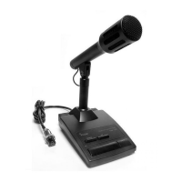
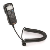
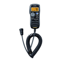
This document describes a modification for desk microphones, specifically the Icom SM-20, to add LED indicators for power-on and Push-To-Talk (PTT) engagement. The modification aims to provide visual feedback to the user, addressing the common issue of not knowing if a microphone is powered or if the PTT is accidentally locked in transmit without looking at the radio or RF output meter.

Function Description:

The core function of this modification is to provide clear visual indicators for two states of a desk microphone:

  1. Power-On Indication: A green LED illuminates when power is supplied to the microphone, indicating that the device is active and ready for use.
  2. PTT Engaged Indication: A red LED illuminates when the PTT switch is pressed or locked, signaling that the microphone is transmitting.

The circuit achieves this using a pair of NPN transistors (Q1 and Q2) configured for polarity reversal, along with resistors and a Schottky diode (D1). When the microphone is powered, Q2 is ON and Q1 is OFF, illuminating the green LED. When the PTT switch is engaged, it grounds the cathode of D1, which in turn turns Q2 OFF and Q1 ON, illuminating the red LED. This design ensures that only one LED is active at a time, clearly indicating the current state.

The modification is designed to be small and unobtrusive, fitting within the microphone's base. It can utilize either a single bi-color red/green LED or two separate, cross-connected LEDs of chosen colors. The author recommends green for power-on and red for PTT engaged.

Important Technical Specifications:

  • Power Source: The circuit is designed to operate with the microphone's power source, typically +5 V or +8 V DC, with a maximum current of 25 mA.
  • LED Forward Current: Resistors R1 and R3 set individual LED forward currents. R5 is used to set the overall LED forward current for desired brightness. For +8 V systems (like the Icom SM-20), R5 is 100 Ω, providing a nominal 10 mA LED current. For +5 V systems, R5 can be replaced with a wire jumper.
  • Components:
    • Transistors (Q1, Q2): NPN type, such as BC547B, 2N2222, 2N4401, or 2N3904. Pin-out verification per manufacturer datasheet is crucial, as some (e.g., BC547B, 2N2222) may require 180-degree mounting compared to others (e.g., 2N4401, 2N3904).
    • Diode (D1): Schottky diode, 1N5819.
    • Capacitors: C1 (2.2 µF 16 V tantalum) and C2 (0.01 µF 50 V ceramic).
    • Resistors: R1 (220 Ω), R2 (3.3 kΩ), R3 (270 Ω), R4 (4.7 kΩ), R5 (100 Ω or jumper for 5V). All resistors are 5% 1/4 W.
    • LED (LED1): Bi-color 3mm red/green LED (e.g., Jameco #94553 or Digikey #160-1058-ND) or two separate 3mm LEDs.
  • Microphone Connections (Icom SM-20 example):
    • +8 V: Pin 2 (red wire)
    • PTT: Pin 5 (yellow wire)
    • Chassis Ground: Pin 6 (black wire)
    • Users should verify continuity from the eight-pin round plug to the microphone's internal PCB solder lands for their specific microphone and radio combination.
  • PCB Dimensions: The author's PCB measures 1.2 x 0.73 inches, designed to fit within the SM-20 microphone base.

Usage Features:

  • Clear Visual Feedback: The primary feature is the immediate visual confirmation of microphone status, eliminating guesswork.
  • Customizable LED Colors: While red/green is recommended, users can choose other color combinations for two separate LEDs (e.g., blue/yellow) to accommodate color blindness.
  • Compact Design: The circuit is designed to be small enough to fit inside the microphone base without significantly altering its external appearance.
  • Professional Appearance: The guidelines emphasize making modifications look professionally done to maintain the microphone's value.

Maintenance Features:

  • Component Replacement: Standard electronic components are used, making replacement straightforward if any part fails.
  • LED Replacement: LEDs are connected with flexible wires, allowing for easier replacement if they burn out or if the user wishes to change colors.
  • Minimal Mechanical Modification: The only mechanical modification required is drilling a small (7/64 inch) hole for the LED(s) and securing them with hot-melt glue. This minimizes irreversible changes to the microphone housing.
  • Circuit Board Accessibility: The PCB is designed to fit into an accessible corner of the microphone base, simplifying installation and any future troubleshooting.
  • Documentation: Gerber files for the PCB layout and additional construction details are available on the QST in Depth web page, allowing users to fabricate their own PCBs or obtain pre-made ones from the author.

Guidelines for Installation:

  • Professionalism: Modifications should appear professionally done to preserve the microphone's value.
  • PTT Switch Protection: Avoid running excessive LED current through the PTT switch, as these are often small tactile switches rated for less than 20 mA. The circuit design ensures current is handled by transistors, not the PTT switch directly.
  • Power Source Protection: Do not overload the radio microphone power source. The circuit is designed to draw appropriate current.
  • LED Mounting: Use small, unobtrusive 3mm LEDs. Drill a 7/64 inch hole, carefully enlarge it for a snug fit, and secure with hot-melt glue from the underside.
  • Wiring: Use flexible #24 or #26 AWG insulated wires for LED connections. Shorten LED leads to about half an inch and use shrink tubing for insulation.
  • Color Blindness Consideration: For users with red-green color blindness, using two separate LEDs spaced apart (e.g., green and red, or blue and yellow) allows differentiation by position rather than color alone, similar to traffic signals.

Icom SM-20 Specifications

General IconGeneral
BrandIcom
ModelSM-20
CategoryMicrophone
LanguageEnglish

Related product manuals