33.
VOX GAIN
CONTROL
This
control
adjusts
input
signal level via
the
microphone
to
the
VOX circuit.
For
VOX
operation
in SSB,
adjust
the
.
control
so
that
the
VOX circuit will
operate
with
normal
speech.
34.
VOX DELAY (VOX
time
constant)
CONTROL
This
controls
the
transmit
to
receive switching time. Ad-
just
it
so
transmit
to
receive switching will
not
occur
during
short
pauses in normal speech.
35.
ANTI-VOX
CONTROL
In
VOX (SSB)
operation,
the
VOX circuit
may
be
operated
by
sound from
the
speaker causing a switch
to
transmit.
This
trouble
can
be
prevented
by
adjusting
the
input
level
of
the
ANTI-VOX circuit
with
this
control
along with
the
VOX gain
control
so
that
the
VOX circuit
only
operates
from
the
operator's
voice,
not
by
.sound from
the
speaker.
36.
N.B. WIDTH SWITCH
Switches
the
blanking
action
time
of
the
noise blanker
NARROW (short) and WIDE (long).
Set
the
switch in
the
NARROW
or
WIDE position according
to
incoming noise.
37.
CW
MONITOR
(MONn
CONTROL
This
control
adjusts
the
audio
volume
of
the
side
tone
(monitor)
audio
during ON
transmit
operation.
Adjust
it
to
your
desired level
for
easy listening.
38.
FREQUENCY
SET
CONTROL
This
control
is
for
fine
adjustment
of
the
reference fre-
quency
of
the
PLL
unit,
which
is
local oscillator frequency.
Do
not
turn
it
unless
you
want
to
change
the
frequency.
REAR PANE L CONNECTIONS
39.
MEMORY BACKUP (RL) TERMINAL
For
connection
of
a 9 -
12V
DC
power
supply.
Formobile
installation
connection
to
the
vehicle's
battery
can
be
made
'.
the
current
drain
is
low,
for
fixed installation use
of
the
BC·10A
is
recommended.
By
changing an internal
connector,
this terminal
can
be
used
for
Transmit/Receive relay
control
terminal. This
terminal can be used
to
switch
24V
1A
DC.
Don't
exceed
this limit.
40.
EXTERNAL
ALC
TERMINAL
This terminal
can
be used
for
input
terminal
of
external
ALC signal
from
a linear amplifier
or
transverter.
By
using
optional
adapter,
IC-EX205
and
changing internal
connectors,
this terminal
can
be
used
for
TRANSVERTER
terminal.
VHF and UHF
operation
using a suitable transverter
with
the
IC-730
is
possible. This terminal
is
for Transverter
connection.
The
output
is
a few milliwatts.
41.
EXTERNAL
SPEAKER
JACK
When an external speaker
is
used,
connect
it
to
this jack.
2-4
Use a speaker
with
an impedance
of
8 ohms. When
the
external speaker
is
connected,
the
built-in speaker
does
not
function.
42_ KEY JACK
For
ON
operation,
connect
the
key here.
For
electronic
keying
the
terminal v.oltage
must
be
less
than
0.4V
DC.
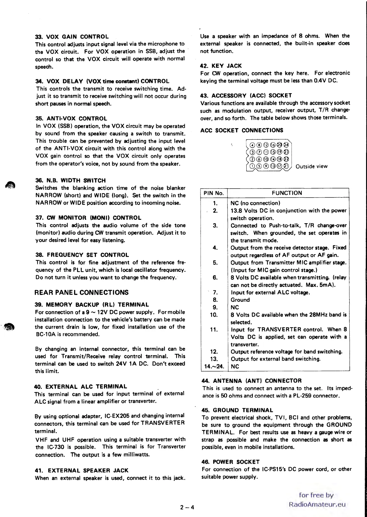
43.
ACCESSORY (ACC) SOCKET
Various
functions
are available
through
the
accessory
socket
such as
modulation
output,
receiver
output,
T
/R
change-
over,
and
so
forth.
The
table
below shows
those
terminals.
ACC
SOCKET CONNECTIONS
PIN
No.
1.
2.
3.
4.
5.
6.
7.
8.
9.
10.
11.
12.
13.
14.-24.
0®@@@@
00@@@@
Q)@@@@@
CD
0 ®
@@
@ Outside view
FUNCTION
NC (no
connection)
13.8
Volts DC in
conjunction
with
the
power
switch
operation.
Connected
to
Push-to-tal k, T
/R
change-over
switch.
When
grounded,
the
set
operates in
the
transmit
mode.
Output
from
the
receive
detector
stage. Fixed
output
regardless
of
AF
output
or
AF gain.
Output
from
Transmitter
MIC amplifier stage.
(Input
for MIC gain
control
stage.)
8 Volts DC available
when
transmitting. (relay
can
not
be directly
actuated.
Max. 5mA).
Input
for external ALC voltage.
Ground
NC
8 Volts DC available
when
the
28MHz
band
is
selected.
Input
for
TRANSVERTER
control.
When 8
Volts DC
is
applied,
set
can
operate
with
a
transverter.
Output
reference voltage
for
band
switching.
Output
for external
band
switching.
NC
44.
ANTENNA (ANT) CONNECTOR
This
is
used
to
connect
an
antenna
to
the
set. Its imped-
ance
is
50
ohms
and
connect
with
a PL-259
connector.
45.
GROUND
TERMINAL
To
prevent electrical shock,
TVI,
BCI
and
other
problems,
be sure
to
ground
the
equipment
through
the
GROUND
TERMINAL.
For
best results use as heavy a gauge wire
or
strap
as possible and
make
the
connection
as
short
as
possible, even in mobile installations.
46.
POWER SOCKET
For
connection
of
the
IC-PS15's DC
power
cord,
or
other
suitable
power
supply.
for
free
by
RadioAmateur.eu
 Loading...


