4-4g
4-3 TRANSMIT ADJUSTMENTS
ADJUSTMENT ADJUSTMENT SETUP OPER ATION
ADJUSTMENT
ITEM/POINT
VALUE
VDD VOLTAGE
~Preset~
1 Set the preset value on the
adjustment screen.
[F5] 200
2 [F6]
3 [F7]
~Adjustment~ 4 CH No.: [AM Low]
No audio signals are applied to
the MIC line.
Transmitting
Connect the RF power
to the antenna connector.
Connect the digital voltmeter
to the CP2 on the MAIN unit.
[F14]
(Adjustment screen)
For IC-A210:
14.5 V
(±0.2 V)
For IC-A210E:
13.0 V
(±0.2 V)
For IC-A220:
13.5 V
(±0.2 V)
5 CH No.: [AM Mid]
Transmitting
[F15]
(Adjustment screen)
6 CH No.: [AM High]
Transmitting
[F16]
(Adjustment screen)
For only IC-A220:
IDLING CURRENT
~Preset~
1
Set the preset value on the
adjustment screen.
[F5] 0
2 [F6]
3 [F7]
4 [F24]
~Adjustment~ 5 CH No.: [AM Mid]
No audio signals are applied to
the MIC line.
Transmitting
Connect the ammeter
between the transceiver and
the power source.
Record
the flowing
current.
6
[F24]
(Adjustment screen)
Set to the
value so that
the flowing
current
becomes 1.0 A
(±0.1 A) higher
than step 5.
TX OUTPUT
POWER
~Adjustment~
1 CH No.: [AM Low]
No audio signals are applied to
the MIC line.
Transmitting
Connect the RF power meter
to the antenna connector.
[F5]
(Adjustment screen)
For IC-A210/
IC-A220:
8.0 W
(±0.2 W)
For IC-A210E:
6.0 W
(±0.2 W)
2 CH No.: [AM Mid]
Transmitting
[F6]
(Adjustment screen)
3 CH No.: [AM High]
Transmitting
[F7]
(Adjustment screen)
(Replacement page)
July 2019
Continued on the next page…
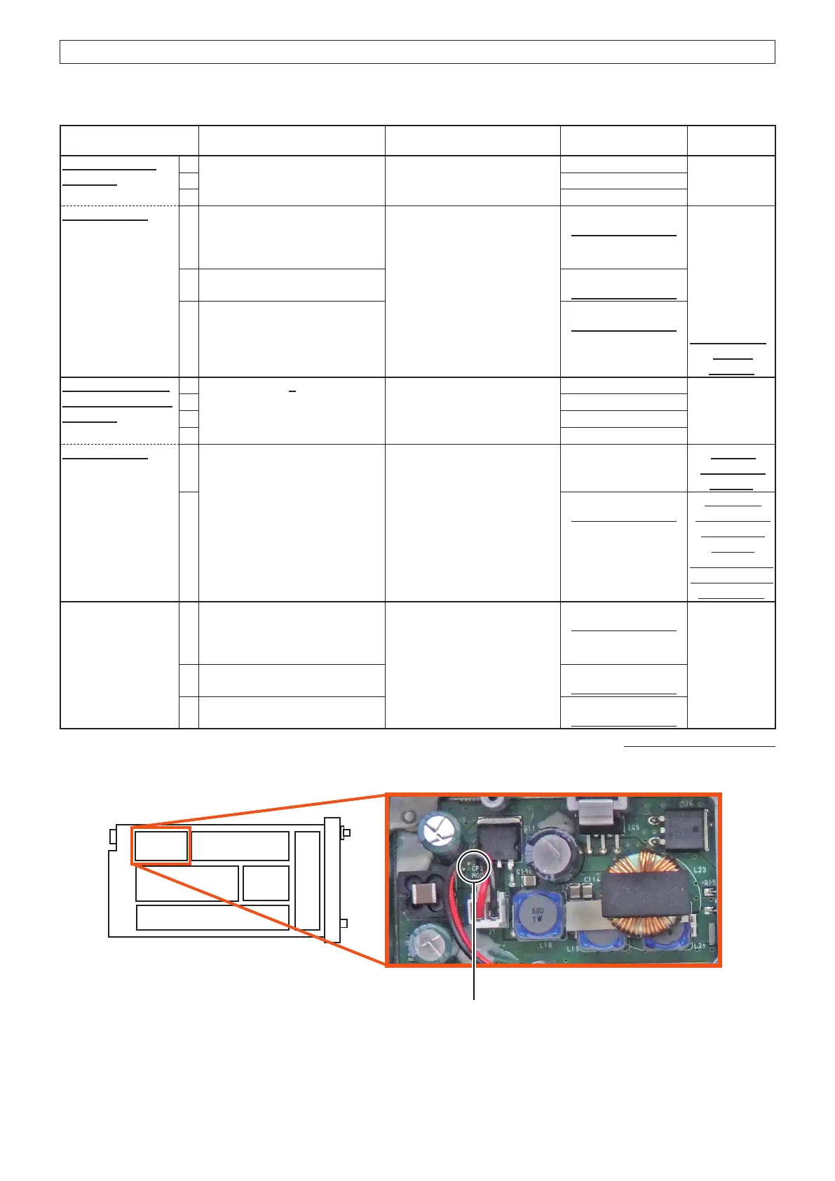
• VDD voltage check point
(TOP VIEW)
CP2
VDD voltage check point
The underlined parts have been updated from the previous version of the addendum, or the original page.

 Loading...


