The actual configuration of the PC board can be seen by viewing the top and bottom BOARD LAYOUT pages together.
See the PARTS LIST H/V location on the PARTS LIST for location details.
7-7g
The underlined parts have been updated from the previous version of the addendum, or the original pages.
(Amended page)
July 2019
1
1
CP4
CP5
W1
R19
J3
CP2
J6
R11
L1
J4
ANT
C2
D5
J7
GND
F1
A
S
B-6663K
C7
R10R8
C19
C24
D3
R15
C10
C1
R2
C13
C22
D1
R13
C23
D2
R14
C28
F1
R1
C12
C25
D4
R16
C6
R7
C18
C27
D6
C4
R5
C16
C21
C9
R12
C2
J4
R3
C14
C3
R4
C15
C20
C8
R9
C5
R6
C17
C26
D5
R17
C11
J7
H0H5H10H15H20H25H30H35H40H45H50H55H60H65H70H75H80H85H90H95H100H105H110H115H120H125H130
V0 V5 V10 V15 V20 V25 V30 V35
CP3
RXD
MIC1
MIC2
MGND
HP
SP
AGND
INCOM
PTT
SGND
TXD
AUX IN
REM
113
J4
DC IN
GND
J3
1
ANTENNA CONNECTOR
(J1: CHASSIS)
W1 (CHASSIS)
W7
(CHASSIS)
To PA/PA-EUR UNIT J503
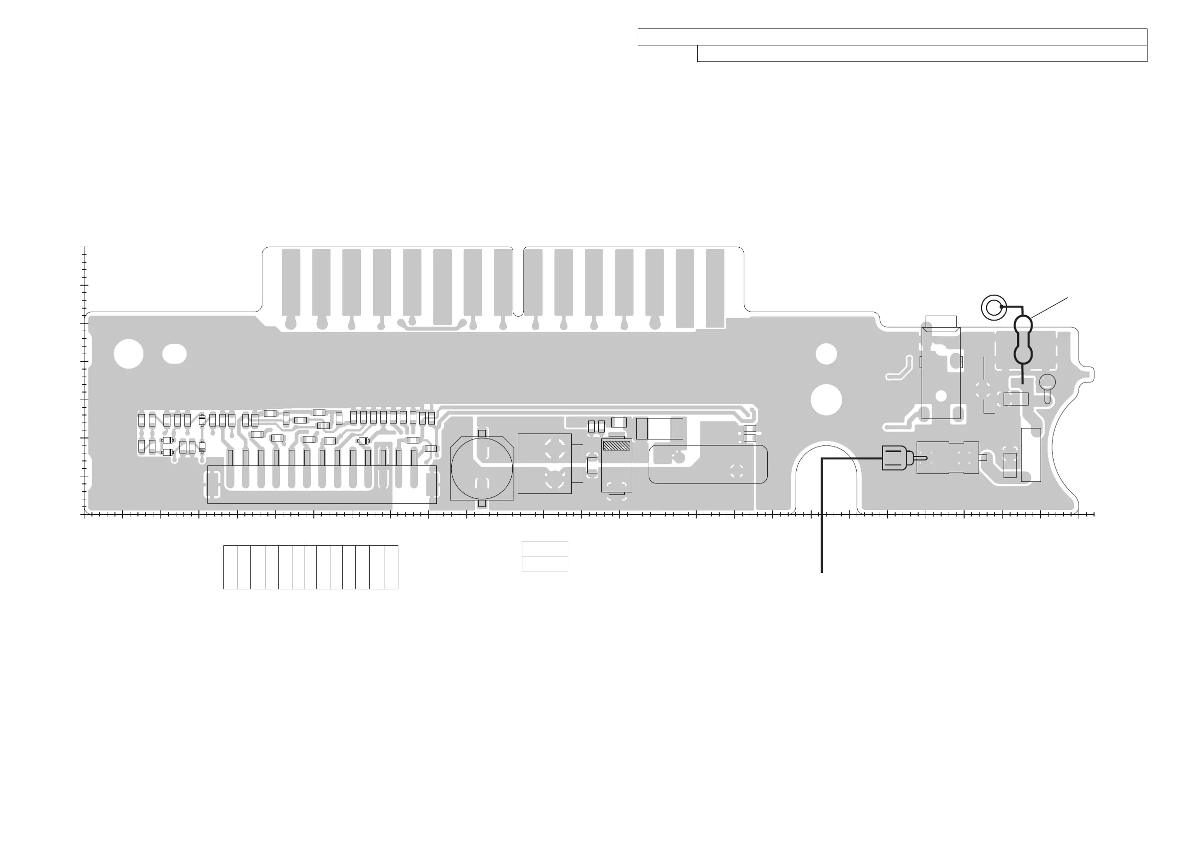
• K-CONNECT UNIT (B6663K for IC-A210 and IC-A210E: Top view)

 Loading...


