27
4
CONNECTION AND MAINTENANCE
4
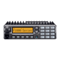
nMounting the transceiver
The universal mounting bracket supplied with your transceiver
allows overhead mounting.
• Mount the transceiver securely with the 4 supplied screws to
a thick surface which can support more than 1.5 kg.
Nut
*Felts reduce the vibration effects.
Felt*
Felt*
Flat washer
Spring washer
When using
self-tapping screws
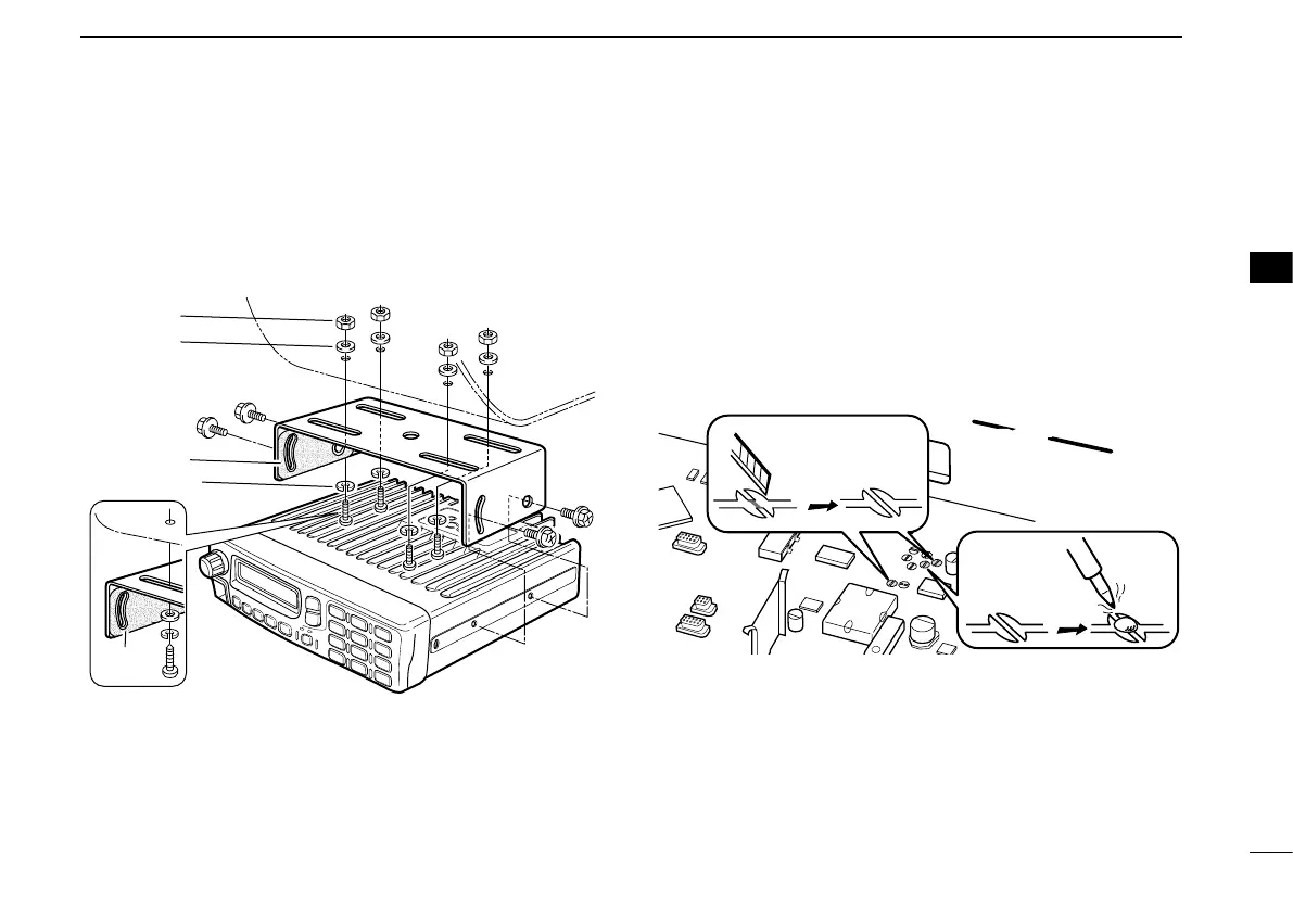
n Optional UT-109 or UT-110
installation
Install the optional UT-109 or UT-110 unit as follows:
q Turn the power OFF, then disconnect the DC power cable.
w Unscrew the 4 cover screws, then remove the bottom
cover.
e Cut the pattern on the PCB at the TX mic circuit (MIC) and RX
AF circuit (AF OUT), then solder CP37 as shown below.
FRONTFRONT
MIC and AF OUT
CP37
☞ Continued on the next page.
 Loading...