EasyManua.ls Logo

Icom IC-F1821D - I Optional UT-109 or UT-110 Installation; I Optional OPC-617 Installation

Icom IC-F1821D
36 pages
Print Icon
To Next Page IconTo Next Page
To Previous Page IconTo Previous Page
Loading...
29
4
CONNECTION AND MAINTENANCE
4
Optional UT-109 or UT-110
installation
q Turn the power OFF, then disconnect the DC power cable.
w Unscrew the 4 cover screws, then remove the bottom cover.
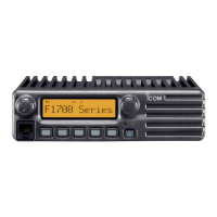
e Cut the pattern on the PCB at the TX mic circuit (MIC) and
RX AF circuit (AF OUT), then solder CP37 as shown below.
r Install the scrambler unit as described in the installation of
optional UT-111 installation on p. 28
t Replace the bottom cover and screws.
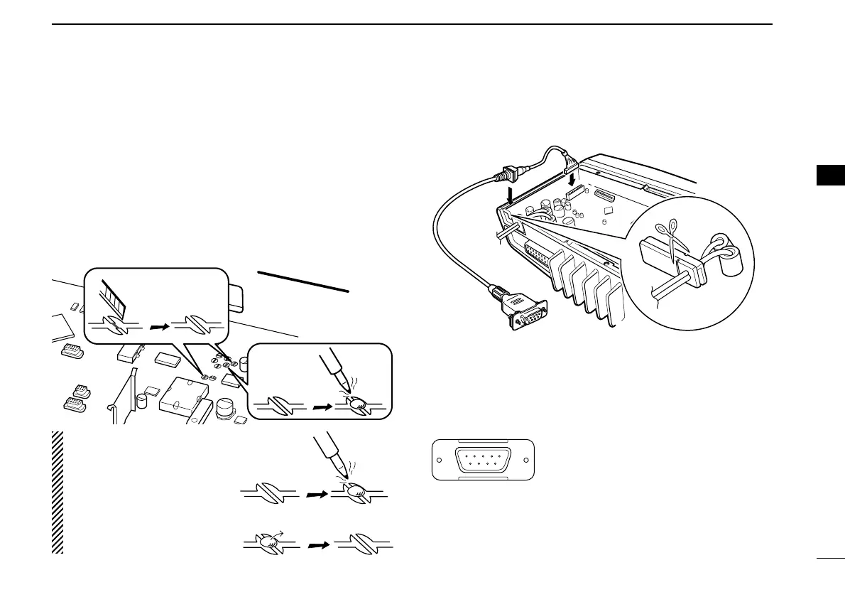
Optional OPC-617 installation
Install the OPC-617 as shown below.
q
Dimmer cont. IN
w AF OUT
e Det. AF OUT
r Mod. IN
t PTT control IN or
y Horn drive cont. OUT
u AF GND
i Det. AF GND
o Mod. GND
OPTIONAL CABLE PIN ASSIGNMENT
t r e w q
o i u y
FTSW control IN
OPC-617
Cut off the bushing as in the
illustration, when you install
the optional OPC-617.
FRONTFRONT
MIC and AF OUT
CP37
Un-solder
Re-solder
Remove
NOTE: When uninstalling
the unit
Be sure to re-solder the
disconnected points and
un-solder the connected
points as above when you
remove the unit. Otherwise
no TX modulation or AF
output is available.

Related product manuals