4-13
4-3 TRANSMIT ADJUSTMENTS (CONTINUED)
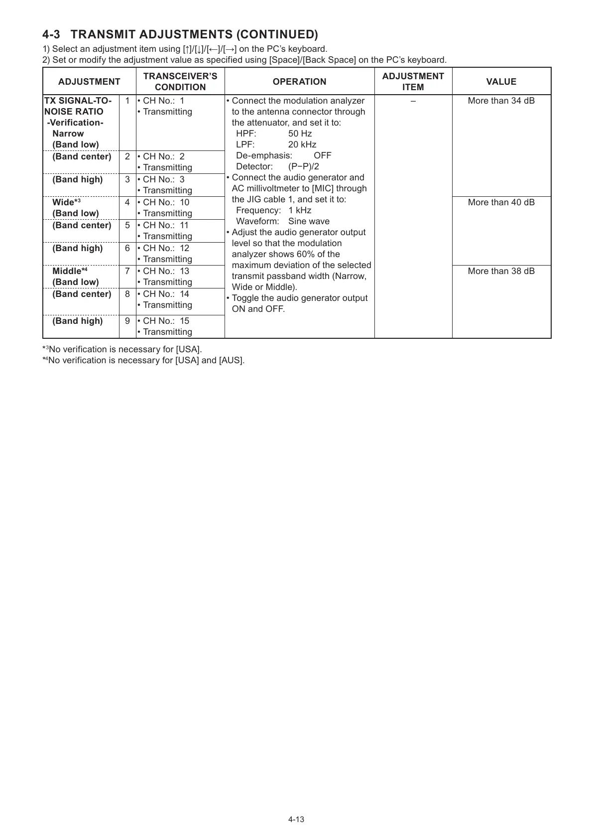
1) Select an adjustment item using [↑]/[↓]/[←]/[→] on the PC’s keyboard.
2) Set or modify the adjustment value as specified using [Space]/[Back Space] on the PC’s keyboard.
ADJUSTMENT
TRANSCEIVER’S
CONDITION
OPER ATION
ADJUSTMENT
ITEM
VALUE
TX SIGNAL-TO-
NOISE RATIO
-Verification-
Narrow
(Band low)
1 • CH No.: 1
• Transmitting
• Connect the modulation analyzer
to the antenna connector through
the attenuator, and set it to:
HPF: 50 Hz
LPF: 20 kHz
De-emphasis: OFF
Detector: (P−P)/2
• Connect the audio generator and
AC millivoltmeter to [MIC] through
the JIG cable 1, and set it to:
Frequency: 1 kHz
Waveform: Sine wave
• Adjust the audio generator output
level so that the modulation
analyzer shows 60% of the
maximum deviation of the selected
transmit passband width (Narrow,
Wide or Middle).
• Toggle the audio generator output
ON and OFF.
– More than 34 dB
(Band center) 2 • CH No.: 2
• Transmitting
(Band high) 3 • CH No.: 3
• Transmitting
Wide*
3
(Band low)
4 • CH No.: 10
• Transmitting
More than 40 dB
(Band center) 5 • CH No.: 11
• Transmitting
(Band high) 6 • CH No.: 12
• Transmitting
Middle*
4
(Band low)
7 • CH No.: 13
• Transmitting
More than 38 dB
(Band center) 8 • CH No.: 14
• Transmitting
(Band high) 9 • CH No.: 15
• Transmitting
*
3
No verification is necessary for [USA].
*
4
No verification is necessary for [USA] and [AUS].
 Loading...