Check the “LV” item on the
CS-F50 ADJ’s display.
Check the “LV” item on the
CS-F50 ADJ’s display.
Loosely couple a frequency
counter to the antenna con-
nector.
Connect an RF power meter
to the antenna connector.
Connect an FM deviation
meter to the antenna connec-
tor through the attenuator.
5 - 4
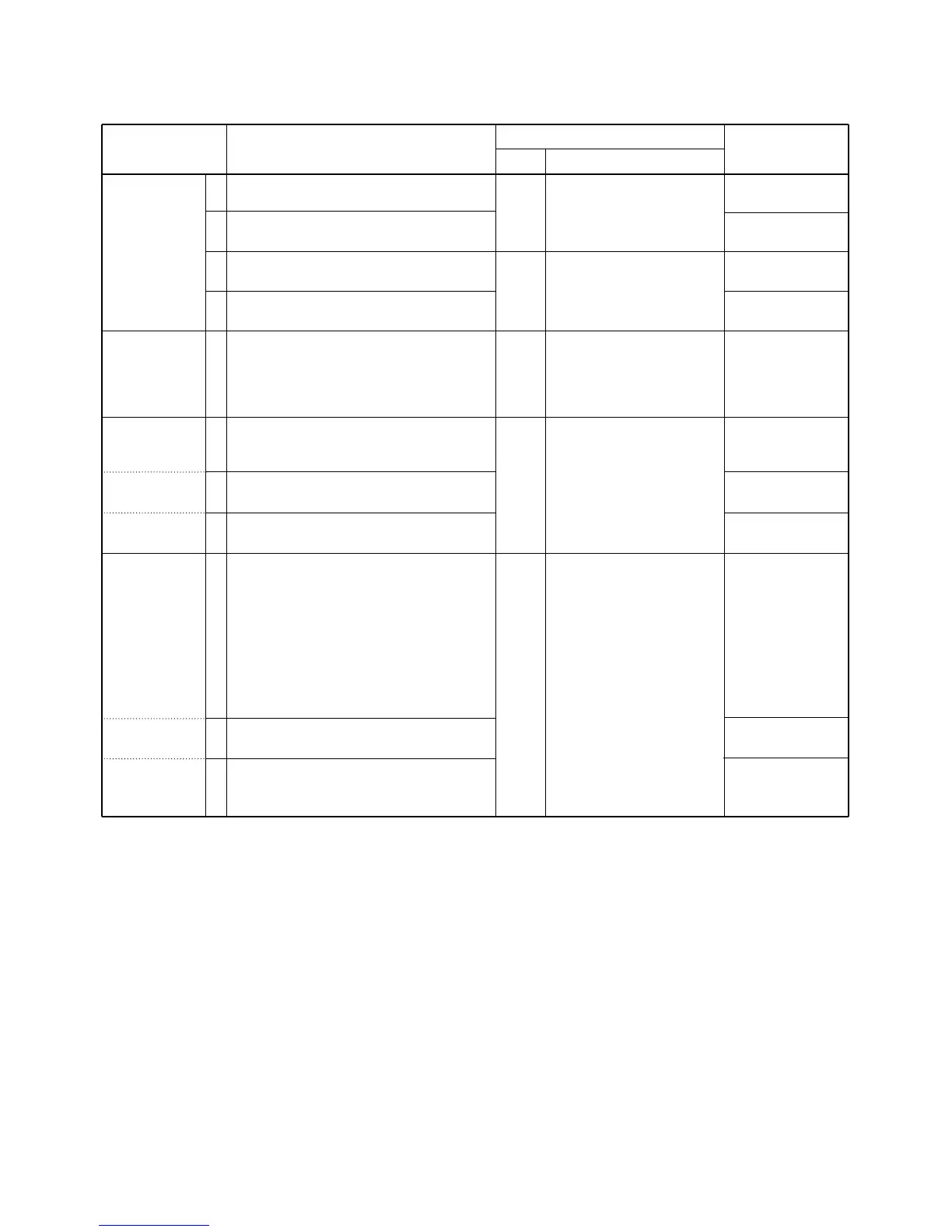
5-2 SOFTWARE ADJUSTMENT (TRANSMITTING)
Select an operation using [↑] / [↓] keys, then set specified value using [←] / [→] keys on the connected computer keyboard.
1
2
3
4
1
1
2
3
1
2
3
• Operating CH : CH3
• Receiving
• Operating CH : CH3
• Transmitting
• Operating CH : CH11
• Receiving
• Operating CH : CH11
• Transmitting
• Operating CH : CH11
• Output power : Low1
• Connect an RF power meter or 50 Ω
dummy load to the antenna connector.
• Transmitting
• Operating CH : CH1
• Transmitting
• Operating CH : CH2
• Transmitting
• Operating CH : CH3
• Transmitting
• Operating CH : CH4
• Set the FM deviation meter as:
HPF : OFF
LPF : 20 kHz
De-emphasis : OFF
Detector : (P–P)/2
• Connect the audio generator to the multi
connector through the JIG cable (*OPC-
966) and set as :
1.0 kHz/150 mVrms
• Transmitting
• Operating CH : CH5
• Transmitting
• Operating CH : CH6
• Transmitting
PLL LOCK
VOLTAGE
[LV (RX LVA)]
[LV (TX LVA)]
REFERENCE
FREQUENCY
[REF]
OUTPUT
POWER
[Power (Hi)]
[Power (L2)]
[Power (L1)]
FM
DEVIATION
[MOD N]
(Narrow)
[MOD Ratio]
(Middle)
[MOD Ratio]
(Wide)
MAIN
MAIN
Top
panel
Top
panel
Top
panel
1.0 V
1.0 V
3.3–4.5 V
(Verify)
3.3–4.5 V
(Verify)
470.0000 MHz [L]
520.0000 MHz [H]
4.0 W
2.0 W
1.0 W
±2.10 kHz
±3.20 kHz
±4.10 kHz
ADJUSTMENT ADJUSTMENT CONDITION
MEASUREMENT
VALUE
UNIT LOCATION

 Loading...