6 - 4
6-2 FREQUENCY ADJUSTMENT
1) Select an adjustment item using cursor or [
↑
] / [
↓
] of the PC’s keyboard.
2) Set or modify the adjustment value as specifi ed using [
←
] / [
→
] of the PC’s keyboard, then push [ENTER].
ADJUSTMENT ADJUSTMENT CONDITION OPERATION VALUE
PLL LOCK
VOLTAGE
-adjustment-
[RX LVA]
1 • Channel
• Receiving
: 1-1 Select the item [RX LVA], then adjust the
voltage (LVIN) using [
←
] / [
→
] of the PC’s
keyboard.
1.3 V
[TX LVA] 2 • Channel
• Transmitting
: 1-1 Select the item [TX LVA], then adjust the
voltage (LVIN) using [
←
] / [
→
] of the PC’s
keyboard.
1.5 V
PLL LOCK
VOLTAGE
-verifi cation-
1 • Channel
• Receiving
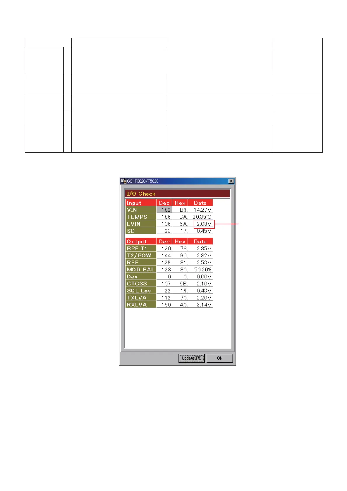
: 1-2 Click [Reload (F5)] button, then check the
“LVIN” item on the “I/O Check window.”
3.2–4.2 V
2 • Channel
• Transmitting
: 1-2 2.8–3.8 V
REFERENCE
FREQUENCY
[REF]
1 • Channel : 1-3
• Connect an RF power meter to the
antenna connector.
• Transmitting
Loosely couple a frequency counter to the
antenna connector.
470.000000 MHz
[Low band]
520.000000 MHz
[High band]
Lock voltage
• I/O Check window
(The values shown in the above screen are example only.
Each transceiver has their own values.)
 Loading...