3-2
3. Removing the DSP-1 and DSP2-A UNITs
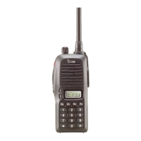
1) Remove the 4 screws from the bottom cover, and
then remove it.
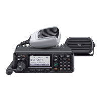
2) Disconnect the 2 fl at cables from the DSP2-A UNIT.
MAIN-A UNIT
J1005
J1005
J1005
J1005
J1005
J1005
J3002
J3002
J4007
J4006
PA
PA-A UNIT
J4001
J3001
J3001
CHASSIS
Bottom cover
Screw ×4
MAIN-A UNIT
J1005
J1005
J1005
J1005
J1005
J1005
J3002
J3002
J4007
J4006
PA
PA-A UNIT
J4001
J3006
J3308
J3305
J3307
Screw ×4
Screw ×6
DSP2-A UNIT
DSP1-A
UNIT
Clip
CHASSIS
INLINE CABLE
MAIN-A UNIT
J1005
J1005
J1005
J1005
J1005
J1005
J3002
J3002
J4007
J4006
PA
PA-A UNIT
J4001
J3001
DSP2-A UNIT
DSP1-A
UNIT
J3002
J8204
J8203
J3001
FLAT
CABLE
flat cable
Carefully pull straight
out on the side tabs to
release the lock.
Pull straight
FLAT CABLE
Flat cable
Flat cable
CAUTION: BE CAREFUL with the tabs,
or they could break.
3) Remove the 4 screws from the DSP2-A UNIT, and
then remove it from the CHASSIS.
4) Remove the clip and 6 screws from the DSP1-A
UNIT.
5) Disconnect the 4 inline cables from the DSP1-A
UNIT.
6) Remove the DSP1-A UNIT from the CHASSIS.
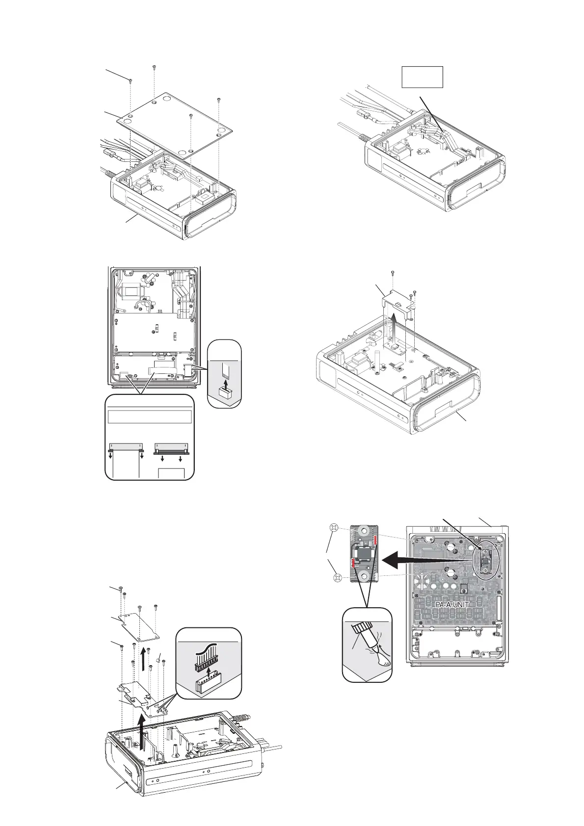
4. Removing the DRIVER-A UNIT
1) Cut the cable tie and remove it.
MAIN-A UNIT
J1005
J1005
J1005
J1005
J1005
J1005
J3002
J3002
J4007
J4006
PA
PA-A UNIT
PA-A UNIT
CHASSIS
DRIVER-A UNIT
Screw ×2
UNSOLDER
Solder
remover
MAIN-A UNIT
J1005
J1005
J1005
J1005
J1005
J1005
J3002
J3002
J4007
J4006
PA
PA-A UNIT
J4001
J3001
J3001
Cable tie
MP45
8950000180
CABLE TIE-80
MAIN-A UNIT
J1005
J1005
J1005
J1005
J1005
J1005
J3002
J3002
J4007
J4006
PA
PA-A UNIT
J4001
J3001
J3001
PA-A UNIT
CHASSIS
PA case
2) Remove 3 screws, and then remove the PA case.
3) Unsolder total of 8 points.
4) Remove 2 screws from the DRIVER-A UNIT.
5) Remove the DRIVER-A UNIT from the CHASSIS.
 Loading...