5-1
SECTION 5
ADJUSTMENT PROCEDURE
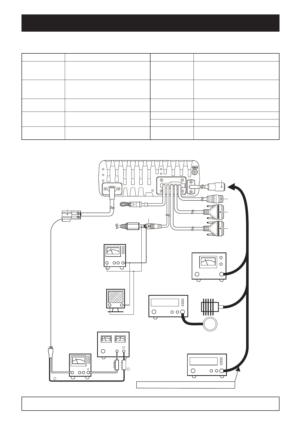
M GENERAL CONNECTION
5-1 PREPARATION
EQUIPMENT GRADE AND RANGE EQUIPMENT GRADE AND RANGE
Cloning software
CS-F8100 CLONING SOFTWARE
(Revision 1.0 or later)
Standard signal
generator (SSG)
Frequency range: 0.1–50 MHz
Output level: –20 dBµ to 90 dBµ
(–127 to –17 dBm)
RF power meter
(50
terminated)
Measuring range: 0.1–300 W
Frequency range: 0.1–50 MHz
SWR: Less than 1.2 : 1
Frequency counter
Frequency range: 0.1–50 MHz
Frequency accuracy: ±1 ppm or better
Input level: Less than 1 mW
AC millivoltmeter Measuring range: 10 mV to 10 V Dummy load
Input impedance: 50
Capacity: More than 300 W
Audio generator
(AG)
Frequency range: 300–3000 Hz
Output level: 1–500 mV
External speaker SP-35L
Voltmeter Measuring range: 0.1–10 V
DC power supply
Voltage: 13.8 V
Capacity: More than 40 A
Ammeter Measuring range: 0.1–40 A
M REQUIRED EQUIPMENTS
To the antenna connector
DUMMY LOAD
(50 Ω/300 W)
RF POWER METER
(300 W/50 Ω)
AMMETER
(0.1–40 A)
Fuses
30 A
DC power supply
(13.8 V/40 A)
⊕
−
Black
Red⊕
Red
⊕
−
Black
−
−
Supplied DC cable
STANDARD SIGNAL GENERATOR
(0.1–50 MHz)
AC MILLIVOLT METER
(10 mV to 10 V)
EXT. SPEAKER
(2 W/8 Ω)
3.5(d) mm monoral plug
+–
+
–
NEVER TRANSMIT while an SSG is connected.
FREQUENCY COUNTER
(0.1–50 MHz)
(Loose Coupling)
USB
ACC
ANT
ATU
DC
SP
The tests described in Section 5 should be measured and adjusted the with above test equipment, or a radio
tester. The adjustments are described with the radio tester.
 Loading...