Do you have a question about the Icom IC-R70 and is the answer not in the manual?
Details semiconductor counts, frequency coverage, control, readout, stability, power, impedance, weight, dimensions.
Describes receiving system, modes, IF frequencies, center frequency, sensitivity, selectivity, spurious rejection, audio output.
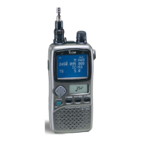
Identifies and explains front panel controls and indicators of the IC-R70 receiver.
Details rear panel connectors, switches, and terminals for external connections.
Provides a block diagram illustrating the interconnection of RF and Main units.
Block diagram showing the PLL and Logic unit interconnections and signal flow.
Detailed explanation of the RF unit's circuit stages and operation.
Describes main unit circuits, including IF stages, other circuits like noise-blanker, AGC, and AF stage.
Details the composition and operation of the PLL unit, including LO circuits.
Explains the logic unit's function, CPU, and control of frequency and modes.
Displays voltage diagrams and circuit operations for the unit's display.
Presents voltage diagrams and circuits for the regulator unit.
Provides step-by-step instructions and diagrams for disassembling the unit.
Identifies and lists parts associated with the front panel assembly.
Identifies and lists parts located on the rear panel assembly.
Provides procedures for adjusting PLL loop lock and frequency calibration.
Details adjustments for receiver total gain, S-meter, and noise blanker.
Continues receiver adjustments, focusing on PBT frequency and monitor operation check.
Outlines adjustment procedures for receiving gain, discriminator, and FM tuning.