EasyManua.ls Logo

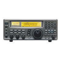
Icom IC-R75 Service Manual

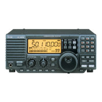
Icom IC-R75
51 pages
To Next Page IconTo Next Page
Page #1 background imageLoading...
Page #1 background image
SERVICE
MANUAL
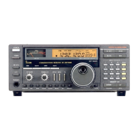
COMMUNICATIONS RECEIVER

Other manuals for Icom IC-R75

Questions and Answers:

Icom IC-R75 Specifications

General IconGeneral
BrandIcom
ModelIC-R75
CategoryReceiver
LanguageEnglish

Summary

DANGER

SECTION 1 SPECIFICATIONS

SECTION 3 CIRCUIT DESCRIPTION

3-1 RECEIVER CIRCUITS

Explanation of the RF switching, filtering, and pre-amplifier circuits.

3-2 PLL CIRCUITS

Description of the Phase-Locked Loop (PLL) system and its circuits.

3-3 LOGIC CIRCUITS

Description of the CPU and associated logic circuits.

3-4 POWER SUPPLY CIRCUITS

Details on the various voltage lines and their functions within the unit.

3-5 PORT ALLOCATIONS

Pin assignments and functions for the CPU and other connectors.

SECTION 4 ADJUSTMENT PROCEDURES

4-1 PREPARATION

Required test equipment and connection setup for adjustments.

4-2 PLL ADJUSTMENT

Procedure for adjusting the Phase-Locked Loop (PLL) circuits for frequency stability.

4-3 RECEIVER ADJUSTMENTS

Procedures for adjusting receiver sensitivity, mixer balance, and other RF parameters.

4-4 SET MODE ADJUSTMENT

Instructions for entering and performing set mode adjustments.

SECTION 9 BLOCK DIAGRAM

SECTION 10 VOLTAGE DIAGRAM

10-1 FRONT UNIT

Voltage diagram for the Front Unit, showing power distribution.

10-3 MAIN UNIT

Voltage diagram for the Main Unit, detailing power distribution.

Related product manuals