B
Brian FrederickJul 27, 2025
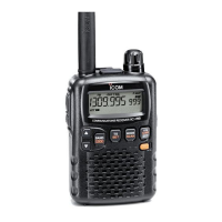
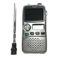
What to do if my Icom IC-R5 seems to be malfunctioning?
- AAnthony LongJul 27, 2025
If your Icom Receiver seems to be malfunctioning, here are some things you can try: Replace or charge the batteries, check the battery polarity, push [Y] to adjust the level, or adjust the squelch level by pushing [SQL] while rotating [DIAL]. You can also try turning off any unnecessary functions, including the attenuator function (push [FUNC], then [SQL]) or other functions (push [FUNC], then [BAND• ] for 1 second). If these steps don't help, try re-installing the batteries (wait at least 1 second), then plug in the AC adapter while pushing [FUNC].
