SECTION 4 CIRCUIT DESCRIPTION
4 - 1
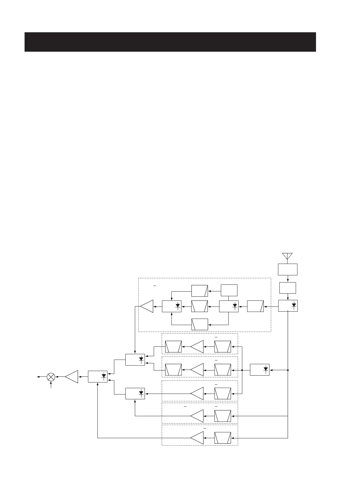
4-1 RECEIVER CIRCUITS
4-1-1 BAND SWITCHING CIRCUIT (RF UNIT)
The RF signals from the antenna connector pass through the
limitter (D68) and an attenuator (D69). The signals are then
applied to the antenna switching circuit (D13, D31, D73, D75)
which suppress out-of-band signals.
4-1-2 RF CIRCUIT (RF UNIT)
The RF circuit amplifies the received signals within the range
of frequency coverage and filters out-of-band signals.
(1) 0.150 MHz–29.999 MHz
RF signals (0.150–29.999MHz) from an band switching cir-
cuit (D73) pass through a low-pass filter (C511–C515, L81,
L82). The filtered signals are amplified at an RF amplifier
(Q505) passing through each filters depending on the receiv-
ing frequency. The amplified signals are then applied to the
1st mixer circuit (IC1, pin 1) after being amplified at another
RF amplifier (IC11) via the band switching diode (D71).
The signals below 1.9 MHz pass through a low-pass filter
(C534, C535, C657, C658, L88, L89) via the band switching
diode (D66), and are then applied to the RF amplifier circuit
(Q505) via the band switching diode (D67).
The 1.9 MHz–14.995 MHz signals pass through the band
switching diode (D65) and bandpass filter (C522–C531,
L85–L87, L91), and are then applied to the RF amplifier cir-
cuit (Q505) via the band switching diode (D70).
The 15 MHz–29.995 MHz signals pass through the band
switching diode (D63) and high-pass filter (C516–C520, L83,
L84) and are then applied to the RF amplifier circuit (Q505)
via the band switching diode (D64).
(2) 118 MHz–174.995 MHz, 330 MHz–832.995 MHz
RF signals (118 MHz–174.995 MHz, 330 MHz–832.995
MHz) from an antenna switching diode (D75) are passed
through each bandpass filter and RF amplifier, and are then
applied to the 1st mixer circuit (IC1) via the band switching
diode (D71) and RF amplifier (IC11).
The 118 MHz–174.995 MHz signals pass through the band
switching diode (D74) and low-pass filter (C8–C13, C67,
C416, L14, L57–L59, L70), and are then amplified at RF
amplifier (Q14). The amplified signal passes through the tun-
able band-pass filters (D1, D2) and band switching diode
(D25).
The 330 MHz–469.995 MHz signals are amplified at RF
amplifier (Q35) via the band switching diode (D3) and band-
pass filter (C19–C23, C216, L2–L5). The amplified signal
passes through the tunable band-pass filters (D4, D5) and
band switching diode (D29).
The 470 MHz–832.995 MHz signals are amplified at RF
amplifier (Q24) via the band-pass filter (C32, C33, C35–C37,
C39, C145), between the band switching diode (D11, D32).