B
brooksmelissaJul 26, 2025
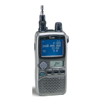
How to fix a program scan that does not operate on my Icom Receiver?
- RRichard WallJul 26, 2025
If the program scan does not operate on your Icom Receiver, it could be due to: * The squelch being open. Set the squelch to the threshold point. * The start and end frequencies being the same. Program different start and end frequencies.