EasyManua.ls Logo

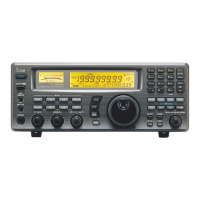
Icom IC-R1500 User Manual

Icom IC-R1500
56 pages
To Next Page IconTo Next Page
Page #1 background imageLoading...
Page #1 background image
INSTRUCTION MANUAL
iR1500
COMMUNICATIONS RECEIVER

Questions and Answers:

Icom IC-R1500 Specifications

General IconGeneral
Antenna ConnectorBNC
Antenna Impedance50 Ω
Power Supply13.8V DC
Modulation ModesAM, FM, SSB, CW
Channels1000
Power13.8 V DC ±15%
Current Consumption1.5 A

Summary

IMPORTANT

Read All Instructions

Read all instructions carefully and completely before using the receiver.

Save Instruction Manual

Save this manual as it contains important operating instructions for the IC-R1500.

EXPLICIT DEFINITIONS

Warning Definition

Personal injury, fire hazard or electric shock may occur.

Caution Definition

Equipment damage may occur.

Note Definition

Recommended for optimum use. No risk of personal injury, fire or electric shock.

FEATURES

Wide Frequency Coverage

Covers a wide frequency range with all receive modes.

Remote and PC Control

Supports both remote controller and PC control applications.

ANF and NR Functions

ANF and NR functions are available with an optional DSP unit.

IF Shift Function

Allows adjustment of the IF shift function.

PRECAUTIONS

AC Outlet Connection Warning

Warning against connecting the receiver via OPC-254L to an AC outlet.

Driving Operation Warning

Warning against operating the receiver while driving a vehicle.

Over 14V DC Power Warning

Warning against connecting to a power source over 14V DC.

Reverse Polarity Power Warning

Warning against connecting to a power source with reverse polarity.

DC Power Cable Cutting Warning

Warning against cutting the DC power cable between the plug and fuse holder.

Environmental Exposure Warning

Warning against exposing the receiver to rain, snow, or liquids.

Wet Hands Operation Warning

Warning against operating or touching the receiver with wet hands.

Placement Hindrance Warning

Warning against placing the receiver where it hinders vehicle operation or causes injury.

Cooling Fan Obstruction Warning

Warning against obstructing the cooling fan on the rear panel.

Temperature and Sunlight Avoidance

Avoid direct sunlight and extreme temperatures (-10°C to +60°C).

Heat During Operation Caution

Caution that the receiver may become hot during prolonged continuous operation.

Ventilation Avoidance

Avoid placing the receiver in areas without adequate ventilation.

Cleaning Agent Avoidance

Avoid using chemical agents like benzine or alcohol for cleaning.

FCC Compliance Caution (USA)

Caution regarding modifications voiding FCC authority to operate.

SUPPLIED ACCESSORIES

SPECIFICATIONS

OPTIONS

UT-106 DSP Unit

Provides AF DSP functions like noise reduction and auto notch.

CP-12L Cigarette Lighter Cables

For operation and charging via a 12 V cigarette lighter socket.

OPC-254L DC Power Cables

For operation and charging via an external power supply.

SP-10 External Speaker

For all-round mobile operation with a 1.5 m cable.

OPC-1156 Separation Cable

For extended separate installation with a 3.5 m cable.

CONNECTION

Rear Panel Connections

Details the rear panel connection of the receiver and its components.

DC Power Supply Connection

Explains how to connect to a 12V DC power supply, emphasizing polarity.

Fuse Replacement

Illustrates the process for replacing fuses in the DC power cable.

OPC-1156 Connection

Provides steps for connecting the OPC-1156 separation cable.

Antenna Installation

Guidance on installing the antenna, including location.

PANEL DESCRIPTION

Set-Lock Switch

Enters set mode or toggles the lock function ON/OFF.

Tuning Step/Mode Switch

Selects tuning step or receive mode.

Volume Control

Adjusts the audio level.

Controller Power Switch

Turns the controller power ON or OFF.

Squelch Control

Varies the squelch level.

Monitor/Tone/Tone Scan Switch

Controls monitor, tone squelch selection, and tone scan.

Noise Blanker/AGC Switch

Toggles Noise Blanker or selects AGC function (Slow/Fast).

Attenuator/Priority Switch

Toggles Attenuator or starts priority watch.

Memory/Skip Switch

Selects memory mode or toggles channel skip setting.

VFO/MHz Tuning-Scan Switch

Selects VFO, toggles band, or starts scan.

Tuning Dial

Selects frequency, memory, set mode items, or scan direction.

Memory Write Switch

Selects memory channel for programming or programs it.

Receiver Power Switch

Turns the receiver power ON and OFF.

AFC Indicator

Appears when the AFC function is in use.

FM Center Indicators

Indicates signal tuning status: not centered or centered.

Receive Mode Indicators

Shows the selected receive mode (SSB, CW, AM, FM).

AGC Indicator

Appears when AGC fast is selected in SSB, CW or AM.

NB Indicator

Appears when the NB function is in use.

DSP Indicator

Appears when the DSP digital filter function is in use.

Frequency Readout

Displays operating frequency, channel names, set mode contents.

Memory Indicator

Appears when memory mode is selected.

Auto Power-Off Indicator

Appears while the auto power OFF function is in use.

Priority Indicator

Appears when priority watch is activated; blinks when paused.

Memory Channel Number Indicators

Shows selected memory channel number or bank initial. 'L' indicates lock.

Skip Indicators

Indicates skip channel or program skip frequency settings.

VSC Indicator

Appears when the VSC function is in use.

Tone Squelch Indicator

Appears when the tone squelch function is in use.

Pocket Beep Indicator

Appears with '▶' or '回' when pocket beep function is in use.

DTCS Squelch Indicator

Appears while the DTCS squelch function is in use.

ATT Indicator

Appears when the ATT function is in use.

Busy Indicator

Appears when a signal is received or squelch is open; blinks for monitor.

S-Meter Indicators

Shows relative signal strength while receiving signals.

Rear Panel - Main Unit

Description of the main unit's rear panel connectors and terminals.

Antenna Connector (ANT)

Connects a 50 Ω antenna with a BNC connector.

Data Jack (PACKET)

Connects to TNC for data communications, supports 9600 bps packet.

USB Connector (USB)

Connects to a PC via the supplied USB cable.

External Speaker Jack (EXT SP)

Connects an 8 Ω external speaker with over 0.5 W audio output.

Controller Connector

Connects to a controller via an extension cable.

Power Jack (DC IN)

Accepts 12 V DC ±15% with the supplied DC power cable.

Ground Terminal (GND)

Connect this terminal to a ground.

SETTING A FREQUENCY

Turning Power ON/OFF

Instructions on how to turn the receiver's power ON and OFF.

Mode Selection

Instructions on selecting VFO or Memory/Weather channel modes.

VFO Modes

Used for setting the desired frequency within the frequency coverage.

Memory Mode/Weather Channels

Information on using memory mode and weather channels.

SETTING A FREQUENCY

Tuning Step Selection

Explains how to change frequency increments using the tuning dial.

Setting a Frequency

Details on setting the frequency using the tuning dial and MHz steps.

SETTING A FREQUENCY

Receive Mode Selection

Explains how to select receive modes like LSB, USB, CW, AM, WFM, and FM.

BASIC OPERATION

Receiving

Steps for setting audio level, squelch, and receiving signals.

Monitor Function

Allows listening to weak signals without disturbing the squelch setting.

Lock Function

Prevents accidental frequency changes and unauthorized function access.

BASIC OPERATION

Attenuator Function

Reduces distortion from strong signals near the desired frequency.

AGC Function

Controls receiver gain for constant audio output despite signal fading.

NB Function

Removes pulse-type noise when in SSB, CW, or AM mode.

BASIC OPERATION

AFC Function

Tunes displayed frequency automatically for off-center FM reception.

VSC Function

Opens squelch only for modulated signals, useful during scanning.

BASIC OPERATION

IF Filter Selection

Selects the IF passband width for different receive modes.

IF Shift Function

Electronically changes IF frequency to reject interference.

BASIC OPERATION

Duplex Operation

Explains duplex communication using two different frequencies for transmit/receive.

MEMORY OPERATION

General Description

Details the 1100 memory channels and 21 memory banks available.

Memory Channel Selection

Steps to select a memory channel for viewing or programming.

MEMORY OPERATION

Programming a Memory Channel

Instructions on how to program VFO settings into a memory channel.

MEMORY OPERATION

Programming Channel Names

How to program alphanumeric names (up to 6 characters) for memory channels.

MEMORY OPERATION

Setting Channel Name Display

How to set the channel name indication to be ON or OFF.

Copying Memory Contents

Transfers memory channel contents to VFO or another memory channel.

Memory to VFO Copy

Transfers memory channel contents to VFO mode.

Memory to Memory Copy

Transfers memory channel contents to another memory channel.

MEMORY OPERATION

Memory Clearing

Procedure to clear (blank) programmed memory contents.

MEMORY OPERATION

Memory Bank Setting

Assigns regular memory channels to desired banks for management.

MEMORY OPERATION

Memory Bank Selection

How to select a desired bank and view its contents.

Transferring Bank Contents

Clears or transfers bank contents to another bank.

SCAN OPERATION

Scan Types

Describes different scan types: Full, Programmed, Memory, Bank scans.

SCAN OPERATION

Scan Start/Stop

Instructions on how to start, stop, and control scanning operations.

SCAN OPERATION

Scan Edges Programming

How to program scan edges (0A/0B to 49A/49B) for programmed scans.

SCAN OPERATION

Skip Scan

Configures settings for skipping channels or frequencies during scans.

Skip Channel/Frequency Setting

Sets memory channels to be skipped during memory or frequency skip scans.

Skip Scan Function Setting

Toggles the skip scan function ON and OFF.

SCAN OPERATION

Scan Resume Condition

Selects scan resume condition as timer or pause scan.

PRIORITY WATCH

Priority Watch Types

Describes three types of priority watch checks for signals.

Priority Watch Operation

Steps to start, stop, and operate priority watch.

POCKET BEEP AND TONE SQUELCH

Pocket Beep Operation

Enables pocket beep for calling, acting as a pager function.

POCKET BEEP AND TONE SQUELCH

Available Tone Frequency List

Lists available CTCSS tone frequencies for pocket beep.

Available DTCS Code List

Lists available DTCS codes for pocket beep.

Calling Station with Pocket Beep

Requires tone frequency or DTCS code for pocket beep calling.

POCKET BEEP AND TONE SQUELCH

Tone/DTCS Squelch Operation

Opens squelch only for signals with matching tone or DTCS code.

Reverse Action for Tone or DTCS Squelch

Configures reverse action where squelch closes on matched tone.

POCKET BEEP AND TONE SQUELCH

Tone Scan

Determines necessary tone frequency or DTCS code by monitoring signals.

SET MODE

General

Overview of set mode operations and item selection.

Set Mode Items

Lists and describes various adjustable settings like beep, power off, display.

Key-Touch Beep Setting

Turns key-touch beep ON or OFF for silent operation.

Beep Output Level

Adjusts beep level from 1 to 9 for key-touch, power-on, pocket beep.

Auto Power OFF Setting

Automatically turns off receiver with beep after a period of inactivity.

Display Dimmer Setting

Adjusts the display lighting condition from levels 1 to 8.

Display Color Setting

Sets display color to amber, yellow, or green.

SET MODE

Display Contrast Setting

Adjusts LCD contrast through 9 levels.

Duplex Direction Setting

Sets duplex direction (OFF, DUP-, DUP+) for frequency shifting.

Offset Frequency Setting

Sets duplex offset frequency for frequency bands (0 to 1000 MHz).

SET MODE

Tone Frequency Setting

Sets subaudible tone frequencies for tone squelch operation.

DTCS Code Setting

Sets DTCS codes for DTCS squelch operation.

DTCS Polarity Setting

Sets DTCS polarities to normal (n) or reverse (r).

SET MODE

VSC Setting

Turns VSC (Voice Squelch Control) function ON and OFF.

Scan Resume Timer Setting

Selects scan resume timer (SCP-2, SCT-15/10/5).

Program Scan Skip Setting

Sets program scan skip ON/OFF for VFO scan.

Scan Skip Area Setting

Sets pre-programmed scan skip area ON/OFF for VFO scan.

Memory Name Setting

Sets memory name display ON or OFF.

SET MODE

Memory Bank Link Function

Sets memory bank link function ON/OFF for continuous bank scans.

AFC Setting

Turns AFC (Automatic Frequency Control) function ON and OFF.

Filter Setting

Selects IF filter passband width (3, 6, 15, 50, 230).

Weather Alert Function

Turns weather alert function ON and OFF (USA/CANADA only).

SET MODE

IF Shift Frequency Setting

Selects IF shift frequency up to ±1.25 kHz in 100 Hz steps.

Squelch Delay Setting

Selects squelch delay (short/long) to prevent repeated squelch opening/closing.

ANF Setting

Turns ANF (Automatic Notch Filter) ON/OFF to attenuate beat tones.

NR Setting

Selects NR (Noise Reduction) level from 1-15 or OFF using DSP.

OTHER FUNCTIONS

Weather Channel Operation (USA/CANADA Versions Only)

Operation of weather channels and alert functions.

Weather Channel Selection

Selects weather channels and groups.

Weather Alert Function

Monitors selected weather channel for alerts and sounds beep tones.

OTHER FUNCTIONS

DSP Operation (Optional UT-106 is Required)

Functions utilizing the optional DSP unit for signal processing.

ANF Function

Attenuates beat tones and tuning signals in SSB, AM, FM modes.

NR Function

Reduces noise and enhances desired signals using DSP.

OTHER FUNCTIONS

DATA Cloning (IC-PCR1500 Control Software Must Be Installed)

Transferring data and programming via PC connection.

Cloning Using Personal Computer

Transfers programmed data to/from a PC using control software.

Available Cloning Functions

Lists functions like reading/writing data, programming settings, mode settings.

OTHER FUNCTIONS

Partial Reset

Initializes operating conditions without clearing memory contents.

All Reset

Resets all memory information and initializes all receiver values.

OTHER FUNCTIONS

Internal Audio Switch

Toggles internal switch for external speaker or headphones/earphone use.

TROUBLESHOOTING

Troubleshooting Guide

Provides common problems, possible causes, and solutions for receiver issues.

DOC

Declaration of Conformity

Declaration of compliance with essential requirements of radio and telecommunications directives.