441 01 2314 06
Specifications are subject to change without notice.
9
3. Other openings are caulked or sealed. These include
joints around window and door frames, between sole
plates and floors, between wall−ceiling joints, between
wall panels, at penetrations for plumbing, electrical and
gas lines, etc.
Ventilation Air
Some provincial codes and local municipalities require ventilation
or make−up air be brought into the conditioned space as replace-
ment air. Whichever method is used, the mixed return air tempera-
ture across the heat exchanger MUST not fall below 60° F(16° C)
continuously, or 55° F(13° C) on an intermittent basis so that flue
gases will not condense excessively in the heat exchanger. Ex-
cessive condensation will shorten the life of the heat exchanger
and possibly void your warranty.
4. Gas Vent Installation
CARBON MONOXIDE POISONING, FIRE AND
EXPLOSION HAZARD
Failure to follow this warning could result in
personal injury, death and/or property damage.
Read and follow all instructions in this section.
!
WARNING
Install the vent in compliance with codes of the country having ju-
risdiction, local codes or ordinances and these instructions.
This Category I furnace is fan−assisted. A fan assisted appliance
is an appliance equipped with an integral mechanical means to ei-
ther draw or force products of combustion through the heat ex-
changer.
Category I furnace definition: A central furnace which operates
with a non−positive vent static pressure and with a flue loss not
less than 17 percent. These furnaces are approved for common−
venting and multi−story venting with other fan−assisted or draft
hood−equipped appliances in accordance with the NFGC or
NSCNGPIC.
Category I Safe Venting Requirements
Category I furnace vent installations shall be in accordance with
Parts 10 and 13 of the National Fuel Gas Code, ANSI
Z223.1/NFPA 54−2009; and/or Section 8 and Appendix C of the
CSA B149.1−05, National Standard of Canada, Natural Gas and
Propane Installation Code; the local building codes; furnace and
vent manufacturer’s instructions.
NOTE: The following instructions comply with the ANSI
Z223.1/NFPA 54 National Fuel Gas Code and CSA B149.1 Natu-
ral Gas and Propane Installation code, based on the input rate on
the furnace rating plate.
1. If a Category I vent passes through an attic, any concealed
space or floor, use ONLY Type B or Type L double wall vent
pipe. If vent pipe passes through interior wall, use Type B vent
pipe with ventilated thimble ONLY.
2. Do NOT vent furnace into any chimney serving an open fire-
place or solid fuel burning appliance.
3. Use the same diameter Category I connector or pipe as per-
mitted by:
• the National Fuel Gas Code Code ANSI Z223.1/NFPA
54−2009 Sections 12 and 13 venting requirements in the
United States,
or
• the National Standard of Canada Natural Gas and Pro-
pane Installation Code (NSCNGPIC) CSA B149.1−05
Section 8 and appendix C venting requirements in Cana-
da.
4. Push the vent connector onto the furnace flue collar of the
venter assembly until it touches the bead [at least
5
/
8
″
(15.9mm) overlap] and fasten with at least two field−supplied,
corrosion−resistant, sheet metal screws located at least 140°
apart.
5. Keep vertical Category I vent pipe or vent connector runs as
short and direct as possible.
6. Vertical outdoor runs of Type−B or ANY single wall vent pipe
below the roof line are NOT permitted.
7. Slope all horizontal runs up from furnace to the vent terminal a
minimum of
1
/
4
″ per foot (10mm/m)
8. Rigidly support all horizontal portions of the venting system ev-
ery 6′ (1.8m) or less using proper clamps and metal straps to
prevent sagging and ensure there is no movement after instal-
lation.
9. Check existing gas vent or chimney to ensure they meet clear-
ances and local codes. See Figure 1
10. The furnace MUST be connected to a factory built chimney or
vent complying with a recognized standard, or a masonry or
concrete chimney lined with a lining material acceptable to the
authority having jurisdiction. Venting into an unlined ma-
sonry chimney or concrete chimney is prohibited. See the
Masonry Chimney Venting section in these instructions.
11. Fan−assisted combustion system Category I furnaces shall
not be vented into single−wall metal vents.
12. Category I furnaces must be vented vertically or nearly verti-
cally, unless equipped with a listed mechanical venter.
13. Vent connectors serving Category I furnaces shall not be con-
nected into any portion of mechanical draft systems operating
under positive pressure.
A 4−to−3 inch (101.6−to−76.2mm) reducer is permitted at the flue
collar when installing a 50,000 BTUH (14.5 kW) gas input furnace,
if the installation meets all the following requirements for sizing the
vent connectors and vents:
1. The National Fuel Gas Code, ANSI
Z223.1/NFPA−54−2009, Sections 12.6.3.1(1),
12.7.3.1(2), 12.11.3.1, 13.1.2, 13.1 (e), and 13.2.24(1)
through (3) in the U.S. or
2. The Natural Gas and Propane Installation Code CSA
B149.1−05, Sections 8.13.1(b), 8.13.2(b), 8.18.5(b), and
Appendix C−GVR no. 2. in Canada.
Venting and Combustion Air Check
NOTE: When an existing Category I furnace is removed or re-
placed, the original venting system may no longer be sized to prop-
erly vent the attached appliances, and to make sure there is
adequate combustion air for all appliances, MAKE THE FOL-
LOWING CHECK.
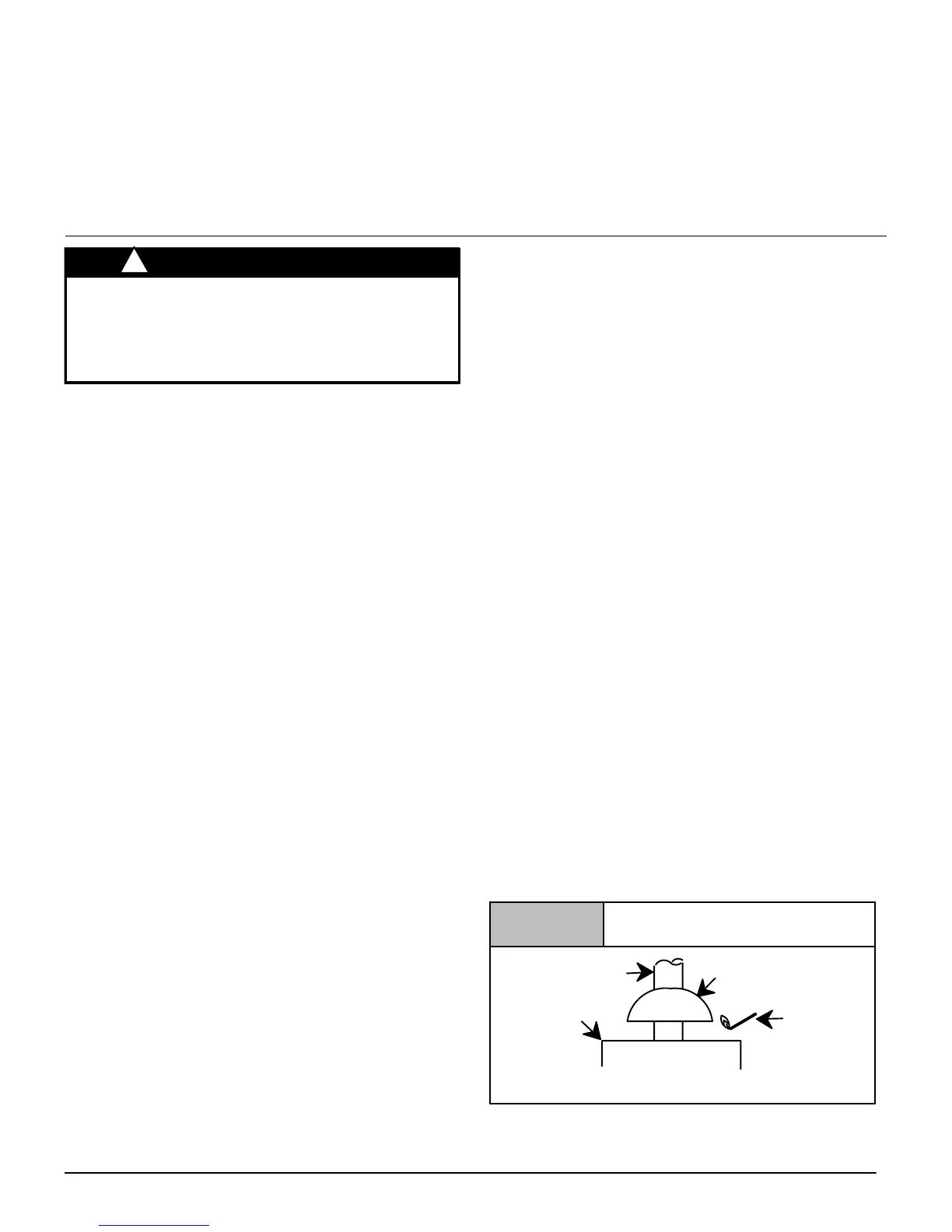
Vent Check
Draft HoodVent Pipe
Match
Typical Gas
Water Heater
Figure 4
NOTE: If flame pulls towards draft hood, this indicates
sufficient infiltration air.