441 01 2314 06
Specifications are subject to change without notice.
22
The redesigned filter bracket needs to be centered on top of the
flanges spanning the depth of the flange opening. Position it so the
“V” portion is between the inner sides of the flanges with the flat
tabs are resting on top of the flange edges. The tabs can then be
bent over the flanges on both ends by hand or by tapping lightly
with a hammer to secure the bracket to the top of the furnace. (see
Figure 17)
No further attachment is necessary. Once the plenum is attached
to the top of the furnace the bracket will not move. The bracket will
look like Figure 17 after being formed onto the flanges.
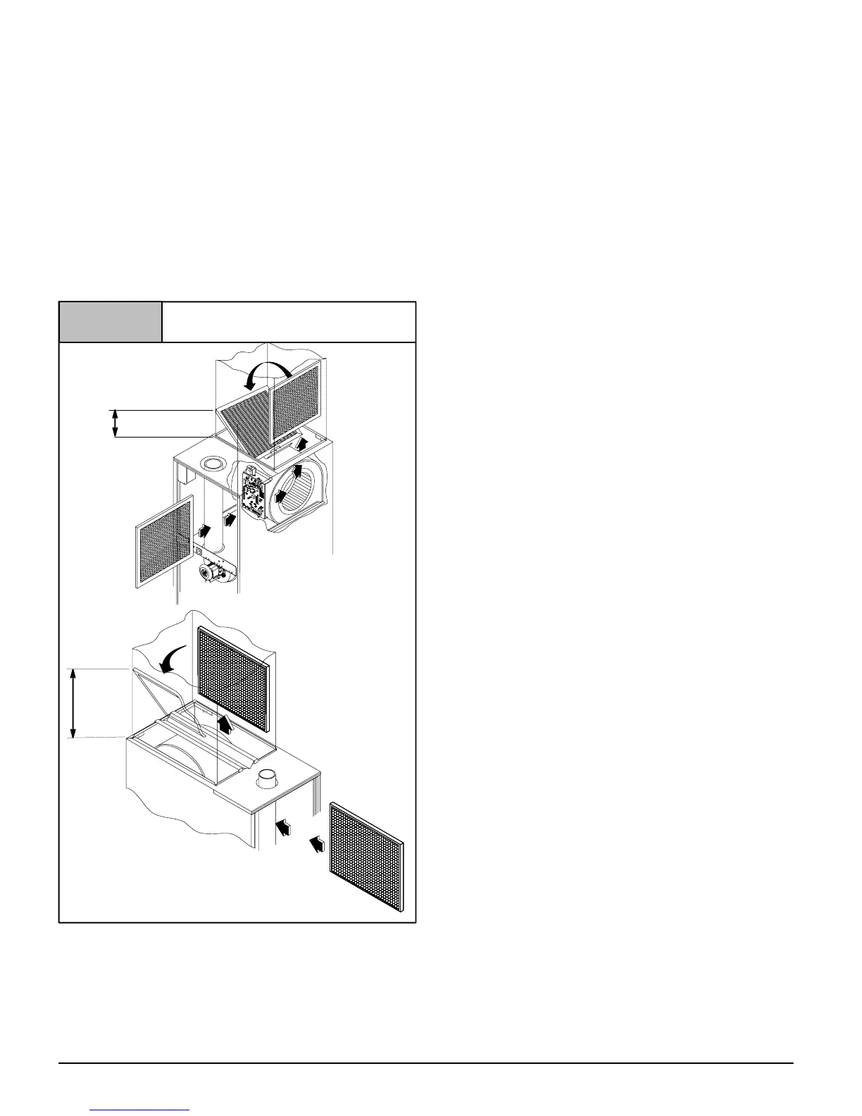
Filter Removal
1. Remove blower compartment door.
2. Reach up above right side of blower and lift dirty filters out of
rack at top of furnace.
16″
“A”
Figure 18
Filter Installation
14″
“A”
25-25-14
OR
Version “A”
Version “B”
(355.6mm)
(406.4mm)
3. Straighten up filters and pull straight down at side of blower.
Pull out through right door opening.
4. Vacuum clean or wash with warm water and dry thoroughly be-
fore replacing.
NOTE: If filters are only suitable for heating application, ad-
vise homeowner that filter size may need to be increased if air
conditioning is added.
Addition Of Air Conditioning
When a refrigeration coil is used in conjunction with this furnace, it
must be installed on the discharge side of the furnace to avoid con-
densation on the heat exchanger. All furnaces are designed with a
break−away duct flange on the supply air side of the furnace. This
allows for installation in the horizontal right or downflow applica-
tions. The coil installation instructions must be consulted for prop-
er coil location and installation procedures. With a parallel flow
arrangement, dampers must be installed to prevent chilled air from
entering the furnace. If manually operated dampers are used, they
must be equipped with a means to prevent operation of either unit
unless the damper is in full heat or full cool position.
Copper or plastic tubing may be used for the condensate drain line.