INSTALLATION INSTRUCTIONS R−410A Split System Air Conditioner
421 01 5104 02 13
Specifications subject to change without notice.
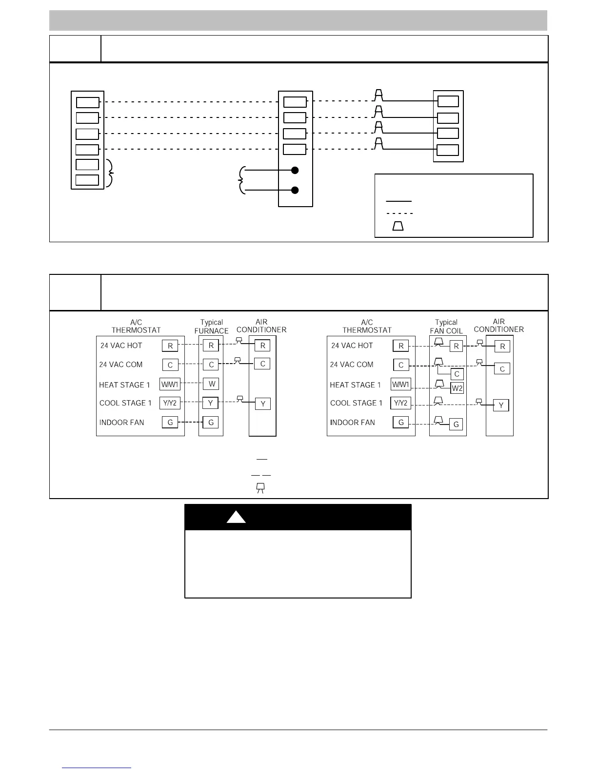
Figure 10
Observer Communicating Wall Control Four−Wire Connection Wiring Diagrams
(See Thermostat Installation Instructions for specific unit combinations)
S1
S2
R
C
DX−
DX+
Optional Remote
Room Sensor
HUM
COM
C
DX−
DX+
Humidifier
Connection
Green
Yellow
White
Red
R
Wall Control
Variable Speed
Furnace/Fan Coil
Outdoor
Green
Yellow
White
Red
LEGEND
24V FACTORY WIRING
24V FIELD WIRING
FIELD SPLICE CONNECTION
C
DX−
DX+
R
Figure 11
Non−Communicating Standard Thermostat 3−Wire 24V Circuit Connections
(See Thermostat Installation Instructions for
Specific Unit combinations)
LEGEND
24−V FACTORY WIRING
24−V FIELD WIRING
FIELD SPLICE CONNECTION
ELECTRICAL OPERATION HAZARD
Failure to follow this caution may result in
equipment damage or improper operation.
A minimum of three wire thermostat wiring is
required for the system to operate.
CAUTION
!