INSTALLATION INSTRUCTIONS R−410A Split System Air Conditioner
14 421 01 5104 02
Specifications subject to change without notice.
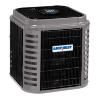
Figure 12
Non−Communicating Standard Thermostat
2−Wire 24V Circuit Connections
R
C
W/W1
Y/Y2
G
G
Y
W
C
R
R
C
Y
FIEL INSTALLED JUMPER WIRE
AIR CONDITIONER
TPPICAL FURNACE
OR
FAN COIL
A/C THERMOSTAT
24VAC HOT
24VAC COM
HEAT STAGE 1
HEAT STAGE 2
INDOOR FAN
LEGEND
24V FACTORY WIRING
24V FIELD WIRING
FIELD SPLICE CONNECTION
NOTE: Wiring must conform to NEC or local codes.
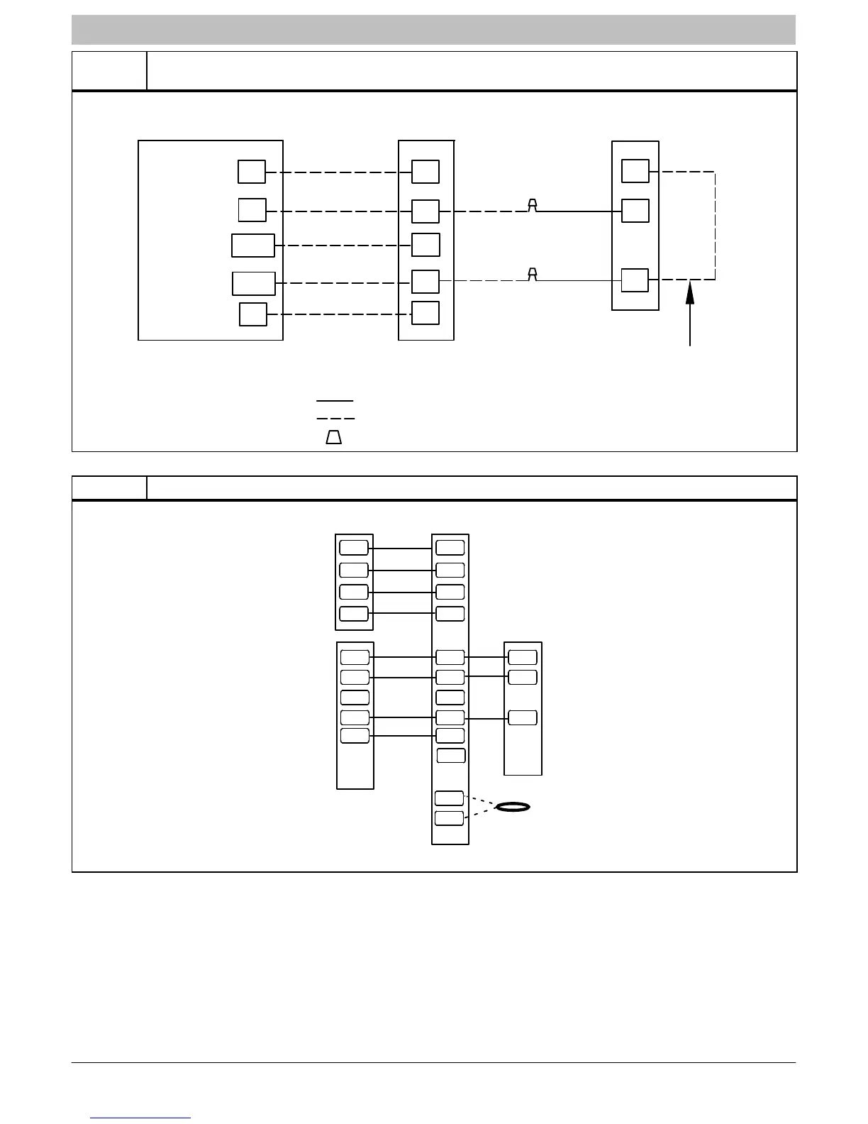
Figure 13 Non−Communicating Indoor with Observer Communicating Wall Control
NAXA00101DB
Green
Yellow
White
Red
OAT
Sensor
Communicating
Outdoor
W2
C
Y
R
C
R
Wall
Control
OAT
DX+
R
C
DX-
Y
G
O
C
Y/Y2
R
W2
G
DX+
R
C
DX-
Non-Communicating
Indoor
NOTE: This installation requires the daughter board
accessory, NAXA00101DB.
NOTE: This installation does not allow for communicating
feature functionality.