SERVICE AND TECHNICAL SUPPORT MANUAL Gas Furnace: (F/G)9MXT
Specifications subject to change without notice.
4 440 04 4321 04
START−UP, ADJUSTMENT, AND SAFETY
CHECK
General
1. Furnace must have a 115-v power supply properly
connected and grounded.
NOTE: Proper polarity must be maintained for 115-v wiring.
Control status indicator light flashes code 10 and furnace does
not operate if polarity is incorrect or if the furnace is not
grounded.
2.
Thermostat wire connections at terminals R, W/W1, G,
and Y/Y2 must be made at 24-v terminal block on
furnace control.
3. Natural gas service pressure must not exceed 0.5 psig
(14-in. w.c., 350 Pa), but must be no less than 0.16 psig
(4.5-in. w.c., 1125 Pa).
4. Blower door must be in place to complete 115-v electrical
circuit and supply power to the furnace components.
UNIT OPERATION HAZARD
Failure to follow this caution may result in intermittent unit
operation or performance dissatisfaction.
These furnaces are equipped with a manual reset limit
switch in burner assembly. This switch opens and shuts off
power to the gas valve if an overheat condition (flame
rollout) occurs in the burner assembly/enclosure. Correct
inadequate combustion-air supply, improper gas pressure
setting, improper burner or gas orifice positioning, or
improper venting condition before resetting switch. DO
NOT jumper this switch.
CAUTION
!
Before operating furnace, check flame rollout manual reset
switch for continuity. If necessary, press button to reset switch.
EAC-1 terminal is energized whenever blower operates. HUM
terminal is only energized when the the gas valve is energized
in heating.
Thermostat Setup Switch
This furnace can be installed with either a single−stage heating
or a two−stage heating thermostat. Setup switch SW−1 (TT) is
used to configure the furnace for single or two stage thermostat
operation. (See Figure 4)
For single−stage thermostats, connect thermostat W to W/W1
at furnace control terminal block. (See Figure 7) For
single−stage thermostats, the control will operate for 12
minutes on low heat, then switch to high heat if heat call
remains. Setup switch SW−1 (TT) must be in the
factory−shipped OFF position. See Figure 7 and Figure 15 for
setup switch information.
If a two−stage heating thermostat is to be used, move setup
switch SW−1 (TT) to ON position before starting furnace. This
overrides built−in control process for selecting high and low
heat and allows the two−stage thermostat to select gas heating
modes. The W2 from thermostat must be connected to W2 on
control terminal block.
Prime Condensate Trap with Water
! WARNING
FIRE OR EXPLOSION HAZARD
Failure to follow these warnings could result in personal injury
or death.
Failure to use a properly configured trap or NOT
water-priming trap before operating furnace may allow
positive pressure vent gases to enter the structure through
drain tube. Vent gases contain carbon monoxide which is
tasteless and odorless.
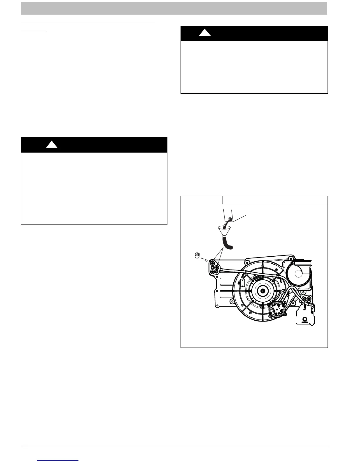
1. Remove upper and middle collector box drain plugs
opposite of the condensate trap. (See Figure 1)
2. Connect field-supplied 5/8-in. (16 mm) ID tube with
attached funnel (see Figure 1) to upper collector box
drain connection.
3. Pour one quart (liter) of water into funnel/tube. Water
should run through collector box, overfill condensate
trap, and flow into open field drain.
4. Remove funnel; replace collector box drain plug.
5. Connect field-supplied 5/8-in. (16 mm) ID tube to middle
collector box drain port.
6. Pour one quart (liter) of water into funnel/tube. Water
should run through collector box, overfill condensate
trap, and flow into open field drain.
7. Remove funnel and tube from collector box and replace
collector box drain plug.
Figure 1 Priming Condensate Drain
L11F065
Representative drawing only, some models may vary in appearance.
Purge Gas Lines
If not previously done, purge the lines after all connections
have been made and check for leaks.