SERVICE AND TECHNICAL SUPPORT MANUAL Gas Furnace: (F/G)9MXT
Specifications subject to change without notice.
12 440 04 4321 04
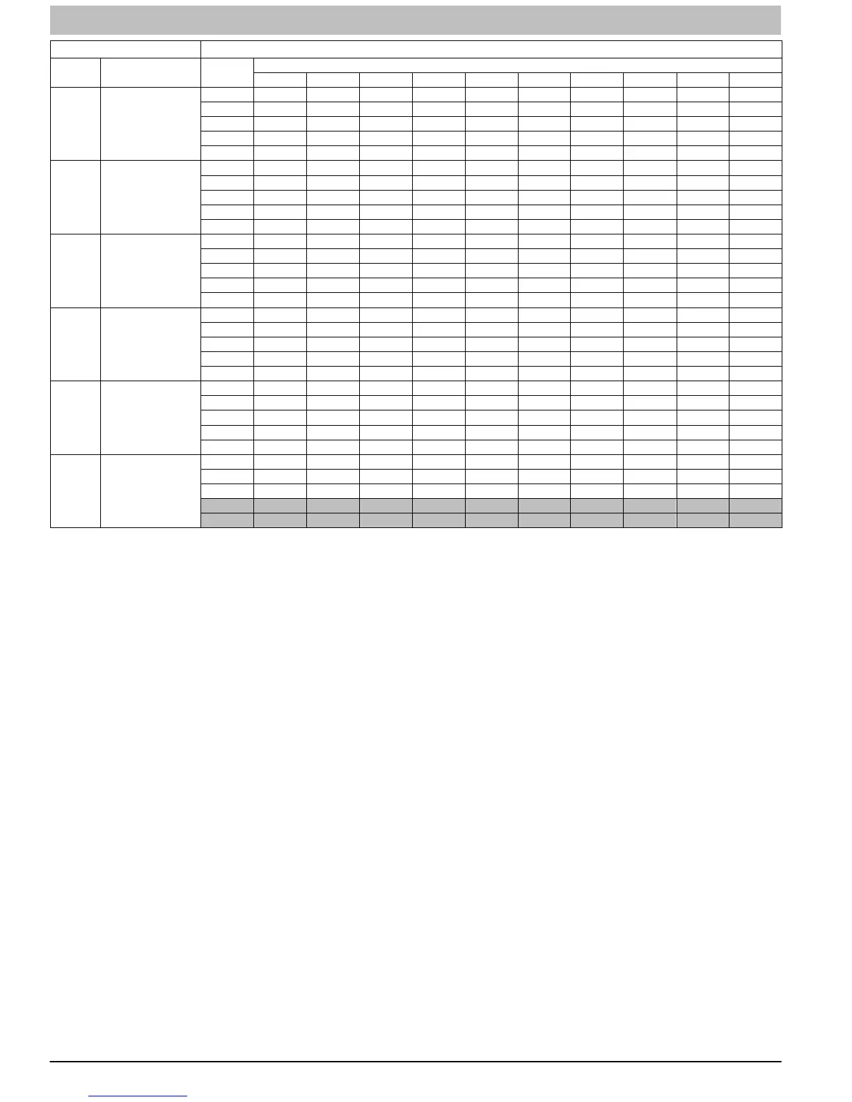
Table 6 AIR DELIVERY - CFM (with filter
1
)
UNIT
SIZE
RETURN-AIR
CONNECTION
SPEED
TAPS
2
EXTERNAL STATIC PRESSURE (IN.W.C.)
0.1 0.2 0.3 0.4 0.5 0.6 0.7 0.8 0.9 1.0
0401410 SIDE/BOTTOM
Gray 1120 1080 1030 980 925 875 820 760 690 630
Yellow 880 845 810 780 740 710 680 640 615 570
Blue 695 665 620 575 535 495 455 420 370 280
Orange 640 595 540 495 460 420 370 310 260 230
Red 570 525 475 425 385 330 255 220 -
6
-
6
0601714 SIDE/BOTTOM
Gray 1720 1670 1620 1565 1505 1440 1375 1295 1220 1135
Yellow 1325 1285 1255 1220 1185 1145 1115 1075 1040 1000
Blue 1010 970 925 875 835 785 745 690 660 620
Orange 1160 1115 1080 1045 1000 960 920 875 840 785
Red 785 715 655 595 530 490 435 385 340 285
0801716 SIDE/BOTTOM
Gray 1810 1770 1720 1665 1610 1540 1475 1400 1315 1235
Yellow 1535 1500 1475 1435 1405 1370 1340 1310 1245 1160
Blue 1380 1340 1305 1270 1240 1200 1165 1130 1090 1050
Orange 1180 1130 1095 1060 1015 975 935 895 850 800
Red 1100 1045 1010 970 920 885 845 790 745 690
0802120
BOTTOM or
TWO-SIDES
4,
5
Gray 2290 2225 2155 2090 2015 1930 1845 1750 1640 1515
Yellow 1810 1760 1725 1685 1640 1600 1555 1520 1480 1415
Blue 1385 1340 1285 1240 1200 1140 1090 1050 995 950
Orange 1560 1520 1475 1430 1385 1335 1295 1240 1200 1150
Red 1055 985 910 860 795 750 680 615 565 495
1002120
BOTTOM or
TWO-SIDES
4,
5
Gray 2340 2295 2250 2195 2110 2030 1935 1835 1725 1605
Yellow 1950 1900 1855 1800 1755 1705 1655 1605 1560 1485
Blue 1750 1700 1650 1605 1555 1500 1455 1395 1350 1300
Orange 1570 1520 1460 1410 1350 1300 1240 1195 1140 1095
Red 1350 1280 1225 1155 1105 1045 1000 950 895 830
1202422
BOTTOM or
TWO-SIDES
4,
5
Gray 2275 2230 2185 2130 2055 1950 1825 1710 1610 1500
Yellow 1875 1820 1770 1720 1660 1600 1550 1505 1450 1390
Blue 2170 2125 2075 2025 1975 1900 1790 1695 1590 1470
Orange
3
1475 1420 1350 1280 1215 1165 1105 1050 995 930
Red
3
1625 1565 1505 1445 1385 1325 1275 1225 1170 1130
NOTE:
1. A filter is required for each return−air inlet. Airflow performance includes a 3/4 in. (19 mm) washable filter media such as contained in factory−authorized accessory
filter rack. See accessory list. To determine airflow performance without this filter, assume an additional 0.1 in. W.C. available external static pressure.
2. ADJUST THE BLOWER SPEED TAPS AS NECESSARY FOR THE PROPER AIR TEMPERATURE RISE FOR EACH INSTALLATION.
3. Shaded areas indicate that this airflow range is BELOW THE RANGE ALLOWED FOR HIGH−STAGE HEATING OPERATION. THESE AIRFLOW RANGES MAY
ONLY BE USED FOR LOW−STAGE HEAT OR COOLING.
4. Airflows over 1800 CFM require bottom return, two−side return, or bottom and side return. A minimum filter size of 20” x 25” is required.
5. For upflow applications, air entering from one side into both the side of the furnace and a return air base counts as a side and bottom return.
6. The ”−” entry indicates an unstable operating condition.
Check Safety Controls
The flame sensor, gas valve, and pressure switch were all
checked in the Start−up procedure section as part of normal
operation.
1. Check Main Limit Switch
This control shuts off combustion system and energizes
air−circulating blower motor, if furnace overheats. By
using this method to check the temperature limit control,
it can be established that the limit is functioning properly
and that the limit will operate if there is a restricted
return−air supply or motor failure. If the limit control does
not function during this test, the cause must be
determined and corrected.
a. Run furnace for at least 5 minutes.
b. Gradually block off return air with a piece of
cardboard or sheet metal until the limit trips.
c. Unblock return air to permit normal circulation.
d. Burners will re−light when furnace cools down.
2. Check Pressure Switch(es)
This control proves operation of the draft inducer blower.
a. Turn off 115−V power to furnace.
b. Disconnect inducer motor lead wires from wire
harness.
c. Turn on 115−V power to furnace.
d. Set thermostat to “call for heat” and wait 1 minute.
When pressure switch is functioning properly, hot
surface igniter should NOT glow and control
diagnostic light flashes a status code 3. If hot surface
igniter glows when inducer motor is disconnected,
shut down furnace immediately.
e. Determine reason pressure switch did not function
properly and correct condition.
f. Turn off 115−V power to furnace.
g. Reconnect inducer motor wires, replace outer door,
and turn on 115−V power.
h. Blower will run for 90 seconds before beginning the
call for heat again.
i. Furnace should ignite normally.
Checklist
1. Put away tools and instruments. Clean up debris.
2. Verify that the jumper is removed from the TEST/TWIN
terminal. Verify that there is nothing plugged into the PLT
connector.
NOTE: Note: If there is a jumper connector plugged into PLT,
remove it and discard. (See Figure 14)
3. Verify that Heating Operating Mode switch SW−1 is set
properly.. (See Figure 14)
4. Verify that the Blower/Heat Off−Delay SW−2 and SW−3
switches are set as desired. (See Figure 14)
5. Verify that the blower (lower door in upflow position) and
control (“Main” or upper door in upflow position) doors
are properly installed.
6. Verify that the Status LED glows. If not, check that the
power supply is energized and that the blower door is
secure. (See Figure 14) to interpret diagnostic codes.
7. Cycle test furnace with room thermostat to be sure that it
operates properly with the room thermostat. Check all
modes including Heat, Cool and Fan.
8. Check operation of accessories per manufacturer’s
instructions.
9. Review Home Owner’s Information with owner.
10. Attach entire literature packet to furnace.
 Loading...