8. DuctworkandFilter
Poison carbon monoxide gas hazard.
Do NOT draw return air from inside a closet or util-
ity room where furnace is located, Return air duct
MUST be sealed to furnace casing,
Failure to properly seal duct can result in personal
injury and/or death,
Duct Connections
This furnace may be installed in only a bottorn or side return ap-
plication. Return air through the back of the unit is NOT allowed.
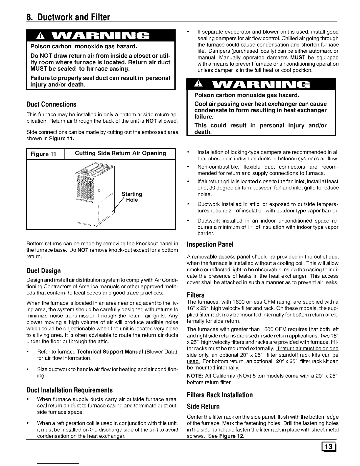
Side connections can be made by cutting out the embossed area
shown in Figure 11.
If separate evaporator and blower unit is used, install good
sealing dampers for air flow control. Chilled air going through
the furnace could cause condensation and shorten furnace
life. Dampers (purchased locally) can be either automatic or
manual. Manually operated dampers MUST be equipped
with a means to prevent furnace or air conditioning operation
unless damper is in the full heat or cool position.
Poison carbon monoxide gas hazard.
Cool air passing over heat exchanger can cause
condensate to form resulting in heat exchanger
failure,
This could result in personal injury and/or
death.
Figure 11 1 Cutting Side Return Air Opening
Starting
• Installation of locking-type dampers are recommended in all
branches, or in individual ducts to balance system's air flow.
• Non-combustible, flexible duct connectors are recom-
mended for return and supply connections to furnace.
• If air return grille is located close to the fan inlet, install at least
one, 90 degree air turn between fan and inlet grille to reduce
noise.
• Ductwork installed in attic, or exposed to outside tempera-
tures require 2" of insulation with outdoor type vapor barrier.
• Ductwork installed in an indoor unconditioned space re-
quires a minimum of 1" of insulation with indoor type vapor
barrier.
Bottom returns can be made by removing the knockout panel in
the furnace base. Do NOT remove knock-out except for a bottom
return.
Duct Design
Design and install air distribution system to comply with Air Condi-
tioning Contractors of America manuals or other approved meth-
ods that conform to local codes and good trade practices.
When the furnace is located in an area near or adjacent to the liv-
ing area, the system should be carefully designed with returns to
minimize noise transmission through the return air grille. Any
blower moving a high volume of air will produce audible noise
which could be objectionable when the unit is located very close
to a living area. It is often advisable to route the return air ducts
under the floor or through the attic.
Refer to furnace Technical Support Manual (Blower Data)
for air flow information.
Size ductwork to handle air flow for heating and air condition-
ing.
Duct Installation Requirements
• When furnace supply ducts carry air outside furnace area,
seal return air duct to furnace casing and terminate duct out-
side furnace space.
• When a refrigeration coil is used in conjunction with this unit,
it must be installed on the discharge side of the unit to avoid
condensation on the heat exchanger.
Inspection Panel
A removable access panel should be provided in the outlet duct
when the furnace is installed without a cooling coil. This will allow
smoke or reflected light to be observable inside the casing to indi-
cate the presence of leaks in the heat exchanger. This access
cover shall be attached in such a manner as to prevent air leaks.
Filters
The furnaces, with 1600 or less CFM rating, are supplied with a
16" x 25" high velocity filter and rack. On these models, the sup-
plied filter rack may be mounted internally for bottom return or ex-
ternally for side return.
The furnaces with greater than 1600 CFM requires that both left
and right side returns are used in side return applications. Two 16"
x 25" high velocity filters and racks are provided with furnace. Fil-
ter racks must be mounted externally. If return air must be on one
side only, an optional 20" x 25" filter standoff rack kits can be
used. For bottom return, an optional 20" x 25" filter rack kit can
be mounted internally.
NOTE: All California (NOx) 5 ton models come with a 20" x 25"
bottom return filter.
Filters Rack Installation
Side Return
Center the filter rack on the side panel, flush with the bottom edge
of the furnace. Mark the fastening holes. Drill the fastening holes
in the side panel and fasten the filter rack in place with sheet metal
screws. See Figure 12.
 Loading...