8. DuctworkandFilter(Upflow/Horizontal)on NTC6/GNEor NTN6/NNE
Poison carbon monoxide gas hazard.
Do NOT draw return air from inside a closet or util-
ity room where furnace is located. Return air duct
MUST be sealed to furnace casing.
Failure to properly seal duct can result in death
and/or personal injury.
Duct Connections
This furnace may be installed in only a bottom or side return ap-
plication. Return air through the back of the unit is NOT allowed.
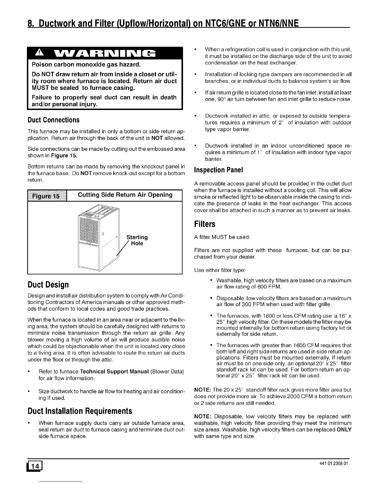
Side connections can be made by cutting out the embossed area
shown in Figure 15.
Bottom returns can be made by removing the knockout panel in
the furnace base. Do NOT remove knock-out except for a bottom
return.
Cutting Side Return Air Opening
Starting
Duct Design
Design and installair distribution system to comply withAir Condi-
tioning Contractors of America manuals or other approved meth-
ods that conform to local codes and good trade practices.
When the furnace is located in an area near or adjacent to the liv-
ing area, the system should be carefully designed with returns to
minimize noise transmission through the return air grille. Any
blower moving a high volume of air will produce audible noise
which could be objectionable when the unit is located very close
to a living area. It is often advisable to route the return air ducts
under the floor or through the attic.
• Refer to furnace Technical Support Manual (Blower Data)
for air flow information.
• Size ductwork to handle air flow for heating and air condition-
ing if used.
DuctInstallationRequirements
• When furnace supply ducts carry air outside furnace area,
seal return air duct to furnace casing and terminate duct out-
side furnace space.
When a refrigeration coil is used in conjunction with this unit,
it must be installed on the discharge side of the unit to avoid
condensation on the heat exchanger.
Installation of locking-type dampers are recommended in all
branches, or in individual ducts to balance system's air flow.
If air return grille is located close to the fan inlet, install at least
one, 90° air turn between fan and inlet grille to reduce noise.
• Ductwork installed in attic, or exposed to outside tempera-
tures requires a minimum of 2" of insulation with outdoor
type vapor barrier.
• Ductwork installed in an indoor unconditioned space re-
quires a minimum of 1" of insulation with indoor type vapor
barrier.
Inspection Panel
A removable access panel should be provided in the outlet duct
when the furnace is installed without a cooling coil. This will allow
smoke or reflected light to be observable inside the casing to indi-
cate the presence of leaks in the heat exchanger. This access
cover shall be attached in such a manner as to prevent air leaks.
Filters
A filter MUST be used:
Filters are not supplied with these furnaces, but can be pur-
chased from your dealer.
Use either filter type:
• Washable, high velocity filters are based on a maximum
air flow rating of 600 FPM
• Disposable, low velocity filters are based on a maximum
air flow of 300 FPM when used with filter grille.
The furnaces, with 1600 or less CFM rating use a 16"x
25" high velocity filter. On these models the filter may be
mounted internally for bottom return using factory kit or
externally for side return.
The furnaces with greater than 1600 CFM requires that
both left and right side returns are used in side return ap-
plications. Filters must be mounted externally. If return
air must be on one side only, an optional 20" x 25" filter
standoff rack kit can be used. For bottom return an op-
tional 20" x 25" filter rack kit can be used.
NOTE: The 20 x 25" standoff filter rack gives more filter area but
does not provide more air. To achieve 2000 CFM a bottom return
or 2 side returns are still needed.
NOTE: Disposable, low velocity filters may be replaced with
washable, high velocity filter providing they meet the minimum
size areas. Washable, high velocity filters can be replaced ONLY
with same type and size.
44t 01 2308 01

 Loading...