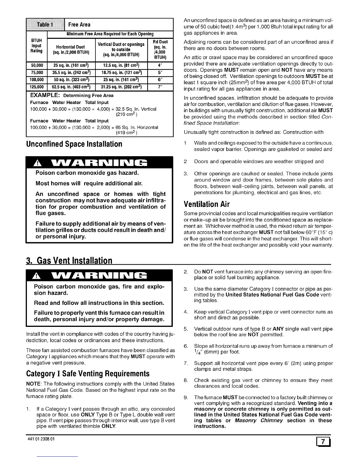
FreeArea
BTUH
Input HorizontalDuct
Rating (sq. in./2,000BTUH)
50,000 25 sq. in.(161cm2)
75,000 35.5 sq. in.(242cm2)
100,000 50 sq. in.(323cm2)
125,000 62.5 sq. in.(403cm2)
VerticalDuctoropenings
to outside
(sq. inJ4,000 BTUH)
12.5 sq. in.(81cm2)
18.75sq. in.(121 cm2)
25 sq.in. (161cm2)
31.25 sq.in. (202cm2)
MinimumFreeAreaRequiredforEachOpening
RdDuct
(sq.in.
/4,000
BTUH)
4"
5"
6"
7"
EXAMPLE: Determining Free Area
Furnace Water Heater Total Input
100,000 + 30,000 = (130,000 + 4,000) =32.5 Sq. In. Vertical
(2t0 cm2)
Furnace Water Heater Total Input
100,000 + 30,000 = (130,000 + 2,000) =65 Sq. In. Horizontal
(4t9 cm2)
UnconfinedSpaceInstallation
An unconfined space is defined as an area having a minimum vol-
ume of 50 cubic feet(1.4m 3)per 1,000 Btuh total input rating for all
gas appliances in area.
Adjoining rooms can be considered part of an unconfined area if
there are no doors between rooms.
An attic or crawl space may be considered an unconfined space
provided there are adequate ventilation openings directly to out-
doors. Openings MUST remain open and NOT have any means
of being closed off. Ventilation openings to outdoors MUST be at
least 1 square inch (25mm 2) of free area per 4,000 BTUH of total
input rating for all gas appliances in area.
In unconfined spaces, infiltration should be adequate to provide
air for combustion, ventilation and dilution of flue gases. However,
in buildings with unusually tight construction, additional air MUST
be provided using the methods described in section titled Con-
fined Space Installation:
Unusually tight construction is defined as: Construction with
1 Walls and ceilings exposed to the outside have a continuous,
sealed vapor barrier. Openings are gasketed or sealed and
Poison carbon monoxide gas hazard.
Most homes will require additional air.
An unconfined space or homes with tight
construction may not have adequate air infiltra-
tion for proper combustion and ventilation of
flue gases.
Failure to supply additional air by means of ven-
tilation grilles or ducts could result in death and/
or personal injury.
2 Doors and openable windows are weather stripped and
Other openings are caulked or sealed. These include joints
around window and door frames, between sole plates and
floors, between wall-ceiling joints, between wall panels, at
penetrations for plumbing, electrical and gas lines, etc.
VentilationAir
Some provincial codes and local municipalities require ventilation
or make-up air be brought into the conditioned space as replace-
ment air. Whichever method is used, the mixed return air temper-
ature across the heat exchanger MUST not fall below 60°F (15 ° c)
or flue gases will condense in the heat exchanger. This will short-
en the life of the heat exchanger and possibly void your warranty.
3. GasVent Installation
Poison carbon monoxide gas, fire and explo-
sion hazard.
2. Do NOT vent furnace into any chimney serving an open fire-
place or solid fuel burning appliance.
Read and follow all instructions in this section.
Failure to properly vent this furnace can result in
death, personal injury and/or property damage.
Install the vent in compliance with codes of the country having ju-
risdiction, local codes or ordinances and these instructions.
These fan assisted combustion furnaces have been classified as
Category [ appliances which means that they MUST operate with
a negative vent pressure.
Category I Safe Venting Requirements
NOTE: The following instructions comply with the United States
National Fuel Gas Code. Based on the highest input rate on the
furnace rating plate.
If a Category [ vent passes through an attic, any concealed
space or floor, use ONLY Type B or Type L double wall vent
pipe. If vent pipe passes through interior wall, use type B vent
pipe with ventilated thimble ONLY.
4.
5.
6.
7.
8.
g.
Use the same diameter Category [ connector or pipe as per-
mitted by the United States National Fuel Gas Code vent-
ing tables.
Keep vertical Category [ vent pipe or vent connector runs as
short and direct as possible.
Vertical outdoor runs of type B or ANY single wall vent pipe
below the roof line are NOT permitted.
Slope all horizontal runs up away from furnace a minimum of
1/4" (6mm) per foot.
Support all horizontal vent pipe every 6' (2m) using proper
clamps and metal straps.
Check existing gas vent or chimney to ensure they meet
clearances and local codes.
The furnace MUST be connected to a factory built chimney or
vent complying with a recognized standard. Venting into a
masonry or concrete chimney is only permitted as out-
lined in the United States National Fuel Gas Code vent-
ing tables or Masonry Chimney section in these
instructions.
441 012308 01 [_
 Loading...
