Ventingand CombustionAir Check
NOTE: Ifthis installation removes an existing furnace from a vent-
ing system serving one or more other appliances, and to make
sure there is adequate combustion air for all appliances, MAKE
THE FOLLOWING CHECK.
1. Seal any unused openings in the venting system.
Visually inspect the venting system for proper size and hori-
zontal pitch to ensure there is no blockage or restriction, leak-
age, corrosion or other deficiencies which could cause an
unsafe condition.
Insofar as is practical, close all doors and windows and all
doors between the space in which the appliance(s) remain-
ing connected to the venting system are located and other
spaces of the building.
Turn on clothes dryers and any appliance not connected to
the venting system. Turn on any exhaust fans, such as range
hoods and bathroom exhausts, so they will operate at maxi-
mum speed. Do not operate a summer exhaust fan. Close
fireplace dampers.
Follow the lighting instructions for each appliance being in-
spected. Adjust thermostat so appliance(s) will operate con-
tinuously.
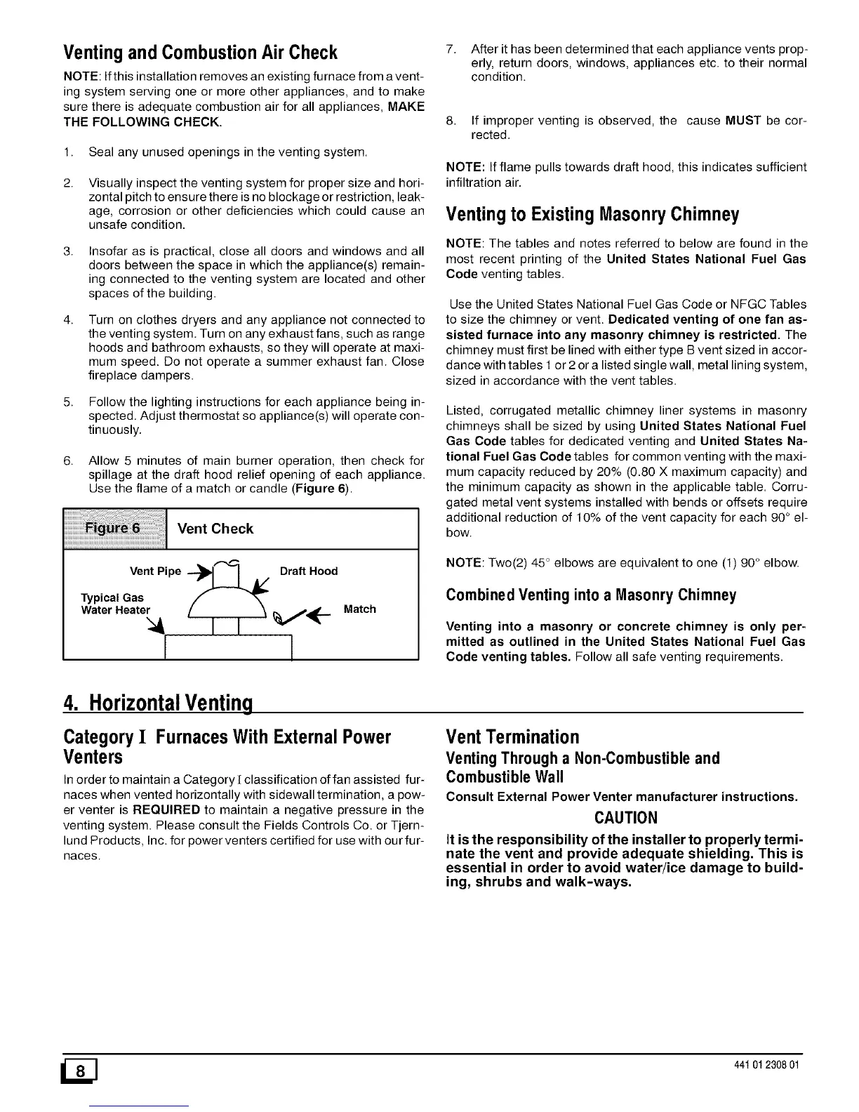
6. Allow 5 minutes of main burner operation, then check for
spillage at the draft hood relief opening of each appliance.
Use the flame of a match or candle (Figure 6).
Vent Check
Vent Pipe ---_1 I A/ Draft Hood
Typical Gas
Water Heater
I I
Match
7. After it has been determined that each appliance vents prop-
erly, return doors, windows, appliances etc. to their normal
condition.
8. If improper venting is observed, the cause MUST be cor-
rected.
NOTE: If flame pulls towards draft hood, this indicates sufficient
infiltration air.
Ventingto ExistingMasonryChimney
NOTE: The tables and notes referred to below are found in the
most recent printing of the United States National Fuel Gas
Code venting tables.
Use the United States National Fuel Gas Code or NFGC Tables
to size the chimney or vent. Dedicated venting of one fan as-
sisted furnace into any masonry chimney is restricted. The
chimney must first be lined with either type B vent sized in accor-
dance with tables 1 or 2 or a listed single wall, metal lining system,
sized in accordance with the vent tables.
Listed, corrugated metallic chimney liner systems in masonry
chimneys shall be sized by using United States National Fuel
Gas Code tables for dedicated venting and United States Na-
tional Fuel Gas Code tables for common venting with the maxi-
mum capacity reduced by 20% (0.80 X maximum capacity) and
the minimum capacity as shown in the applicable table. Corru-
gated metal vent systems installed with bends or offsets require
additional reduction of 10% of the vent capacity for each 90 ° el-
bow.
NOTE: Two(2) 45 ° elbows are equivalent to one (1) 90° elbow.
Combined Venting into a Masonry Chimney
Venting into a masonry or concrete chimney is only per-
mitted as outlined in the United States National Fuel Gas
Code venting tables. Follow all safe venting requirements.
4. HorizontalVenting
Category I FurnacesWith ExternalPower
Venters
Inorder to maintain a Category[ classification offan assisted fur-
naces when vented horizontally with sidewall termination, a pow-
er venter is REQUIRED to maintain a negative pressure in the
venting system. Please consult the Fields Controls Co. or Tjern-
lurid Products, Inc. for power venters certified for use with our fur-
naces.
VentTermination
Venting Through a Non-Combustibleand
Combustible Wall
Consult External Power Venter manufacturer instructions.
CAUTION
It isthe responsibility of the installer to properly termi-
nate the vent and provide adequate shielding. This is
essential in order to avoid water/ice damage to build-
ing, shrubs and walk-ways.
_] 44t 01 2308 01
 Loading...
