iiiiiiiiiiiiiill!!!iiilli;ii!!!!!i_!_!_!_!;!!!!!i!i!iiii!iill ¸iiii¸i¸
iiiiiiiiiiiiiiiiiiiiiiii iiii iii iiii i! i!!ii!ii!i ii ii ii ii ii ii ii ii ii ii ii ii ii ii ii ii ii
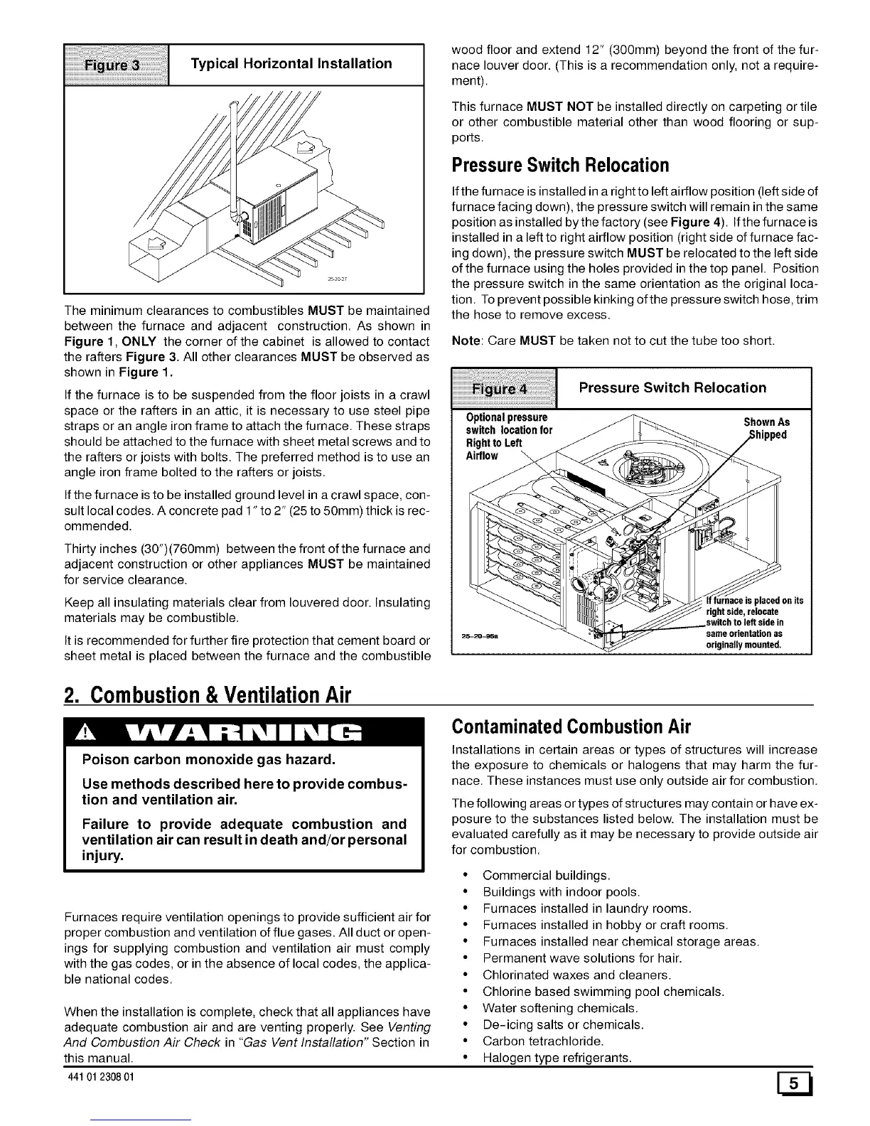
Typical Horizontal Installation
The minimum clearances to combustibles MUST be maintained
between the furnace and adjacent construction. As shown in
Figure 1, ONLY the corner of the cabinet is allowed to contact
the rafters Figure 3. All other clearances MUST be observed as
shown in Figure 1.
If the furnace is to be suspended from the floor joists in a crawl
space or the rafters in an attic, it is necessary to use steel pipe
straps or an angle iron frame to attach the furnace. These straps
should be attached to the furnace with sheet metal screws and to
the rafters or joists with bolts. The preferred method is to use an
angle iron frame bolted to the rafters or joists.
If the furnace is to be installed ground level in a crawl space, con-
sult local codes. A concrete pad 1" to 2" (25 to 50mm) thick is rec-
ommended.
Thirty inches (30")(760mm) between the front of the furnace and
adjacent construction or other appliances MUST be maintained
for service clearance.
Keep all insulating materials clear from Iouvered door. Insulating
materials may be combustible.
It is recommended for further fire protection that cement board or
sheet metal is placed between the furnace and the combustible
wood floor and extend 12" (300mm) beyond the front of the fur-
nace louver door. (This is a recommendation only, not a require-
ment).
This furnace MUST NOT be installed directly on carpeting or tile
or other combustible material other than wood flooring or sup-
ports.
Pressure Switch Relocation
Ifthe furnace is installed in a right to left airflow position (left side of
furnace facing down), the pressure switch will remain in the same
position as installed by the factory (see Figure 4). Ifthe furnace is
installed in a left to right airflow position (right side of furnace fac-
ing down), the pressure switch MUST be relocated to the left side
of the furnace using the holes provided in the top panel. Position
the pressure switch in the same orientation as the original loca-
tion. To prevent possible kinking ofthe pressure switch hose, trim
the hose to remove excess.
Note: Care MUST be taken not to cut the tube too short.
Optionalpressure
switch location for
Rightto Left
Airflow
Pressure Switch Relocation
ShownAs
rightside,relocate
switchto leftside in
sameorientationas
originallymounted.
2. Combustion&VentilationAir
Contaminated CombustionAir
Poison carbon monoxide gas hazard.
Use methods described here to provide combus-
tion and ventilation air.
Failure to provide adequate combustion and
ventilation air can result in death and/or personal
injury.
Furnaces require ventilation openings to provide sufficient air for
proper combustion and ventilation of flue gases. All duct or open-
ings for supplying combustion and ventilation air must comply
with the gas codes, or in the absence of local codes, the applica-
ble national codes.
When the installation is complete, check that all appliances have
adequate combustion air and are venting properly. See Venting
And Combustion Air Check in "Gas Vent Installation" Section in
this manual.
Installations in certain areas or types of structures will increase
the exposure to chemicals or halogens that may harm the fur-
nace. These instances must use only outside air for combustion.
The following areas or types of structures may contain or have ex-
posure to the substances listed below. The installation must be
evaluated carefully as it may be necessary to provide outside air
for combustion.
• Commercial buildings.
• Buildings with indoor pools.
• Furnaces installed in laundry rooms.
• Furnaces installed in hobby or craft rooms.
• Furnaces installed near chemical storage areas.
• Permanent wave solutions for hair.
• Chlorinated waxes and cleaners.
• Chlorine based swimming pool chemicals.
• Water softening chemicals.
• De-icing salts or chemicals.
• Carbon tetrachloride.
• Halogen type refrigerants.
441 012308 01 [_

 Loading...