EasyManua.ls Logo

ICP PHF330000K00A1 - User Manual

ICP PHF330000K00A1
13 pages
Print Icon
To Next Page IconTo Next Page
Loading...
Installation Instructions
PHF3 Series
2 to 4 TON
PACKAGE HEAT PUMPS
TABLEOF CONTENTS
UNITDIMENSIONS......................................... 2
SAFEINSTALLATIONREQUIREMENTS ......................... 3
LOCATINGTHE UNIT ....................................... 3
CLEARANCES ............................................ 3
INSTALLATION............................................ 3
GROUNDLEVELINSTALLATION .............................. 4
ROOFTOPINSTALLATION................................... 4
HOISTING................................................ 4
DOWNFLOWCONVERSION.................................. 4
CONDENSATEDRAIN....................................... 4
ELECTRICALWIRING ................................... 5
DUCTWORK.......................................... 6
FILTERS............................................. 6
AIRFLOWADJUSTMENT ................................ 7
START-UPPROCEDURES ............................... 7
SEQUENCEOF OPERATION.............................. 8
MAINTENANCE ....................................... 9
RIGGING ........................................... 11
WIRINGDIAGRAMS ................................ 12- 13
C_US
°_'_° _°_° LISTED
518 01 1201 01 2-18-09
Printed in U.S.A.
Question and Answer IconNeed help?

Do you have a question about the ICP PHF330000K00A1 and is the answer not in the manual?

Summary

Unit Dimensions

Safe Installation Requirements

Minimum Clearances to Combustible Construction

Specifies minimum distances to prevent fire hazards from combustible materials.

Access Panels

Discusses the location and view of access panels for the unit.

Clearances

Details required air circulation clearances for optimal unit operation and safety.

Installation

Instructions on ensuring the unit is installed level, side-to-side, and front-to-rear.

Ground Level Installation

Requirements for platforms and pads for ground-level unit placement.

Locating the Unit

Rooftop Installation

Platform requirements and structural considerations for roof-mounted installations.

Hoisting

Guidelines for safely lifting and moving the unit using slings and spreader bars.

Downflow Conversion

Steps to convert the unit for downflow airflow applications.

Condensate Drain

Instructions for installing a condensate trap to ensure proper drainage.

Electrical Wiring

Disconnect Switch

Requirements for a field-supplied, waterproof disconnect switch for unit safety.

Ground Connections

Procedures for ensuring a permanent and safe electrical ground connection for the unit.

Line Voltage Wiring

Details on connecting high-voltage power leads to the unit's control box.

Thermostat; Low Voltage Wiring

Guidance on thermostat wiring, including single and two-stage configurations.

Thermostat Heat Anticipator

Explanation of how to adjust the heat anticipator for optimal heating performance.

Ductwork

Ductwork Sizing

Recommendations for sizing ductwork to ensure proper airflow and system efficiency.

Ductwork Insulation

Requirements for insulating outdoor ductwork with fiberglass and a vapor barrier.

Ductwork Connections

Guidelines for sealing ductwork connections to the unit casing to prevent air leaks.

Filters

Importance of filters and recommended sizes for disposable and washable types.

Airflow Adjustment

Circulating Air Blower Speeds

Table and explanation of blower speed tap settings for rated and high airflow.

Blower Tap Connections

Wiring instructions for selecting blower motor speeds for heating and cooling.

Start-Up Procedures

Check Before Starting

Pre-start checks including wiring, filters, access panels, and initial power-up sequence.

Sequence of Operation

Cooling Operation (PHF324-42)

Describes the cooling cycle operation for 2 to 3.5 ton models.

Cooling Operation (PHF348)

Details the two-stage cooling cycle operation for 4-ton models.

Heating Operation (PHF324-42)

Describes the heating cycle operation for 2 to 3.5 ton models.

Heating Operation (PHF348)

Details the two-stage heating cycle operation for 4-ton models.

Scroll Recycle Delay Timer

Explains the compressor delay timer function to prevent reverse rotation.

Continuous Fan Operation

How continuous fan operation is handled based on unit size and thermostat settings.

Defrost Mode

Explanation of the defrost cycle initiation, timing, and operation sequence.

Maintenance

Monthly Maintenance and Inspection Checks

Monthly tasks including checking air filters, condenser coil, and condensate drain.

Cooling Season Checks

Monthly checks for the cooling season, focusing on condenser coil and condensate drain.

Annual Maintenance and Inspection

Annual tasks including cleaning coils, checking fan motors, and blower assemblies.

Rigging Instructions

Rigging Instructions

Guidelines for safely rigging and lifting the unit, including panel placement and spreader bars.

Wiring Diagrams

2 to 3-1;2 Ton Wiring Diagram

Schematic illustrating electrical connections for 2 to 3.5 ton models.

4 Ton Wiring Diagram

Schematic illustrating electrical connections for 4 ton models.

Overview

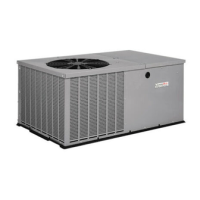
This document provides installation instructions and technical specifications for the PHF3 Series Package Heat Pumps, available in 2 to 4 TON capacities. These units are designed for residential and light commercial heating and cooling applications, offering a self-contained solution that integrates all necessary components into a single outdoor cabinet.

Function Description

The PHF3 Series Package Heat Pumps are unitary air conditioning systems capable of both heating and cooling. They operate by extracting heat from the air in heating mode and rejecting heat in cooling mode, utilizing a refrigerant cycle. The units are designed for either ground-level or rooftop installation and include an indoor fan, outdoor fan, compressor, and a defrost board for managing the defrost cycle in heating mode. The system is controlled by a thermostat, which can be single-stage for 2 to 3.5 Ton models or two-stage for 4 Ton models, allowing for precise temperature regulation.

Important Technical Specifications

  • Capacities: 2 to 4 TON.
  • Electrical Supply: The units are designed for 208/230-1-60 electrical supply. A separate, field-supplied, waterproof disconnect switch is required, mounted at or within sight from the unit. All electrical connections must conform to National Electrical Code (NEC) NFPA 70-2005 or Canadian Electrical Code CSA C.22.1. Only copper conductors are permitted for connections between the disconnect switch and the unit.
  • Thermostat Compatibility: Single-stage thermostats for 2 to 3.5 Ton models, two-stage thermostats for 4 Ton models. Electronic thermostats requiring low voltage for power (C terminal) are supported.
  • Blower Motor: Features multiple speed taps (1, 2, 3, 4) for adjusting airflow in both heating and cooling modes. The blower motor is permanently lubricated and does not require additional lubrication.
  • Condensate Drain: A 3/4" (19.1mm) female PVC connection is located at the bottom left side of the unit. A field-supplied condensate trap with a minimum 2" (50.8mm) standing column of water is required to ensure proper drainage due to negative pressure created by the circulating blower.
  • Defrost System: Equipped with a defrost board that manages the defrost cycle. Defrost interval timing can be configured via dipswitches for 30, 60, 90, or 120 minutes. The backup defrost termination time is fixed at 10 minutes. A compressor recycle delay timer of 5 minutes is integrated to prevent reverse rotation of the scroll compressor.
  • Clearances: Minimum clearances to combustible construction include 2" for duct side (6" on large chassis models), 30" for condenser inlet, blower service (side), control service side (front combustion air inlet), and between a 3 Ft. overhang and the top of the unit. A 0" clearance is allowed for combustible bases (wood or Class A, B or C roof covering material). For units with available filter racks (3.5 to 4 ton), a 26" minimum clearance at the side is needed for filter removal.
  • Ductwork: Maximum recommended velocity in trunk ducts is 1000 ft/min, and in branch ducts is 800 ft/min. Ductwork installed outdoors requires a minimum 2" thick fiberglass "wrap" insulation with a weatherproof vapor barrier.
  • Filters: All return air must pass through a filter. Minimum recommended filter sizes are provided in a table, based on maximum face velocities of 300 ft/min for disposable filters and 500 ft/min for washable filters.

Usage Features

  • Installation Flexibility: Can be installed at ground level on a permanent platform or pad (concrete, bricks, blocks, steel, or pressure-treated timbers) or on a rooftop with adequate structural support. The unit must be level, with a slope no greater than 1/8" per foot (10mm per meter), and the drain side must always be lower.
  • Downflow Conversion: These units are adaptable for downflow applications. Conversion involves removing blockoff plates from the return and supply air compartments and reinstalling them on the horizontal openings.
  • Blower Speed Adjustment: Blower speeds for heating and cooling can be selected by adjusting the wiring on the blower motor's terminal block. This allows for optimization of airflow based on specific application requirements.
  • Two-Stage Operation (4 Ton Models): The 4 Ton models utilize a two-stage thermostat for more efficient heating and cooling. This allows the unit to operate at a lower capacity (first stage) for milder conditions and switch to full capacity (second stage) when demand increases.
  • Continuous Fan Operation: When selected on the thermostat, the indoor fan can run continuously, providing constant air circulation.
  • Quiet Shift Defrost: The defrost system includes a "Quiet Shift" feature, with a 30-second compressor recycle delay during defrost initiation and termination to minimize noise.

Maintenance Features

  • Filter Maintenance: Filters should be inspected at least monthly and replaced or cleaned as required. Dirty filters are a common cause of performance issues and compressor failures. Washable filters can be cleaned with mild detergent and cold water.
  • Condenser Coil Cleaning: The condenser inlet and outlet areas should be kept clean and free of debris. Shrubs should be trimmed to maintain at least 30 inches of clearance from the unit.
  • Condensate Drain Check: The condensate drain should be checked for proper drainage and cleaned as needed.
  • Annual Inspection: An annual inspection is recommended to ensure efficient operation. This includes cleaning the surrounding area, condenser, and evaporator coils. Access panels and the unit top can be removed for easier access.
  • Blower Motor and Wheel Inspection: The blower wheel should be visually inspected for dirt or lint accumulation and cleaned as necessary. The blower motor is permanently lubricated and does not require additional lubrication.
  • Component Access: The control box, containing the defrost board, transformer, contactor, and run capacitor, is accessible for servicing. The blower motor and housing can be removed for maintenance or replacement by following specific steps outlined in the manual.
  • Diagnostic Tools: The defrost board includes jumpered test pins for "speed-up" cycles, allowing technicians to bypass the compressor off delay or force a defrost cycle for diagnostic purposes.

ICP PHF330000K00A1 Specifications

General IconGeneral
BrandICP
ModelPHF330000K00A1
CategoryHeat Pump
LanguageEnglish

Related product manuals