Do you have a question about the ICP PHM336K00A1 and is the answer not in the manual?
Explains the meaning and usage of Danger, Warning, and Caution signal words.
Details the use of signal words like WARNING and CAUTION within the manual.
Illustrates how signal words are combined with colors and pictures on product labels.
Provides detailed dimensions and an illustration of the unit.
Covers essential safety guidelines, including electrical hazards and environmental considerations.
Details proper placement for outdoor installation, considering drainage and environment.
Details minimum clearances for combustible construction, service access, and operational airflow.
Covers general installation notes, slope, access, and the procedure for installing duct collars.
Details the condensate drain outlet, the need for a trap, and proper line routing.
Explains the installation of accessory electric heaters and their associated control packages.
Covers electrical shock hazards, grounding, and proper line voltage wiring techniques.
Step-by-step guide to convert the unit's voltage supply from 230V to 208V.
Covers low voltage wire routing, thermostat connections, and field-installed equipment wiring.
Guides on performing a final check of the electrical system for proper wiring and protection.
Identifies major components within the unit's control box, including boards and transformers.
Provides detailed wiring diagrams for single and dual capacity control boxes.
Shows the physical layout of components within the unit for 2-31/2 ton models.
Explains the wiring diagram legend and provides critical installation notes.
Details DIP switch settings for defrost and speed tap configurations for blower operation.
Shows the physical layout of components within the unit for 4 & 5 ton models.
Explains the wiring diagram legend and provides critical installation notes.
Details DIP switch settings for defrost and speed tap configurations for blower operation.
Provides step-by-step instructions for installing the rain shield on the unit.
Covers ductwork requirements, connections, insulation, and filter specifications.
Details steps for determining and setting the correct blower speed for operation.
Outlines procedures for verifying proper operation during cooling mode.
Lists essential checks to perform before initiating unit operation.
Explains how to adjust the defrost control time interval using DIP switches.
Identifies the defrost control board and its DIP switches for interval selection.
Covers the operational sequences for cooling and heating, including model-specific details.
Explains the unit's operation in continuous fan mode and the defrost sequence.
Mentions the installation of optional low/high pressure and low ambient controls.
Explains the function of the recycle delay timer for compressor protection.
Details the role of low/high pressure switches in protecting the compressor.
Provides cautions regarding operating the unit in specific temperature conditions to prevent damage.
This document provides installation instructions for the PHM3 Series Package Heat Pumps. It covers various aspects from safety labeling and dimensions to electrical wiring, start-up procedures, and operational sequences.
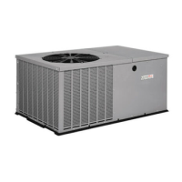
The PHM3 Series Package Heat Pumps are designed for outdoor installation, providing both cooling and heating functions. These units are self-contained, meaning all major components for both heating and cooling are housed within a single cabinet. They are intended to be placed on a ground-level platform, such as a concrete slab or concrete blocks, ensuring proper drainage and clearance from surrounding structures. The units utilize a circulating blower and a condenser fan for air distribution and heat exchange. Electric heat accessories are available to supplement the heating function when required.
| Model Number | PHM336K00A1 |
|---|---|
| Category | Heat Pump |
| Voltage | 208/230V |
| Phase | 1 |
| Refrigerant | R-410A |