P. 4/8
19
20
23
24
21
22
25
26
27
28
29
30
31
32
33
34
35
36
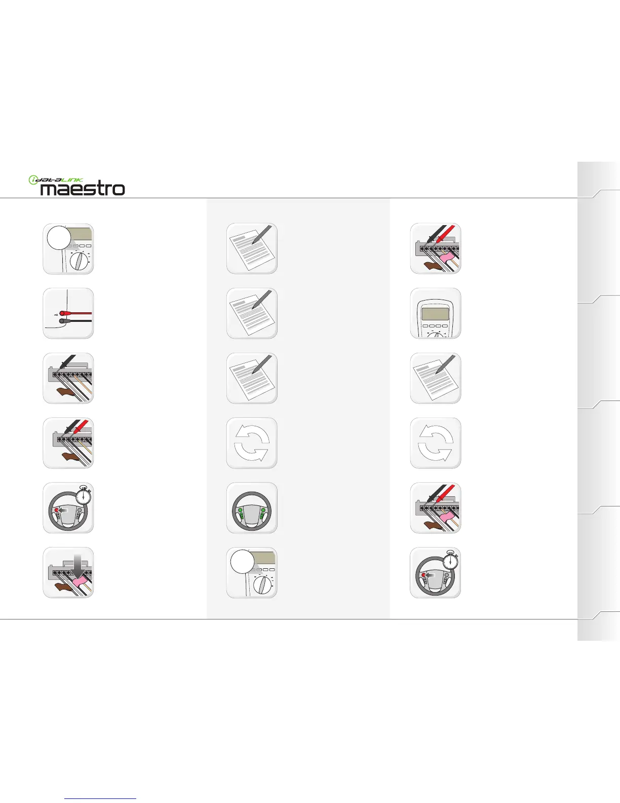
PROGRAMMINGEXTRAS PREPARATIONINSTALLATION
Press and hold for 3 seconds each steering
wheel button, 1 at a time.
When releasing button, look for a change of
resistance on the DMM.
Apply BLACK DMM probe tip to a first wire
with a BROWN SWI F label.
Set DMM to OHMS.
To get an accurate reading: use auto-range
or set the scale at 20k and if reading is less
than 2k, scale down to 2k.
Make sure that DMM is set to OHMS.
Measure resistance value between feed
wire and signal wire.
Record resistance at idle value in section A.
Ensure the probes are connected as shown:
Red probe at input terminal for voltage and
resistance, black probe at common (return)
terminal.
Repeat steps 21 through 27 until all
steering wheel buttons are linked to a
signal and a feed wire.
When DMM displays a change of resistance
apply a PINK SWI label on the wire.
Apply RED DMM probe tip to a first wire of
the radio.
Record in section A the color and location of
the signal wire.
(Wire with a PINK SWI label.)
Record in section B the color and location of
the feed wire.
(Wire with a BROWN SWI F label.)
Record in section C the names of steering
wheel buttons linked to the signal wire.
(Buttons that provided a change of
resistance when pressed and released).
Apply RED DMM probe tip to first signal wire
(PINK label).
Apply BLACK DMM probe tip to linked feed
wire (BROWN label).
One at a time, press and hold each steering
wheel button linked to that signal wire.
Apply RED DMM probe tip to first signal wire
(PINK label).
Apply BLACK DMM probe tip to linked feed
wire (BROWN label).
Radio Wiring (Identifying/Gathering information)
If not all steering wheel buttons are linked,
further testing is required (step 40).
WWW.IDATALINK.COM/SUPPORT
Automotive Data Solutions Inc. © 2012Maestro Install Guide / Vehicles not currently covered
Repeat steps 31 through 33 for each signal
wire.