12.00
V
DC
P. 3/8
01
02
03
04
05
06
07
08
09
10
11
12
13
14
15
16
17
18
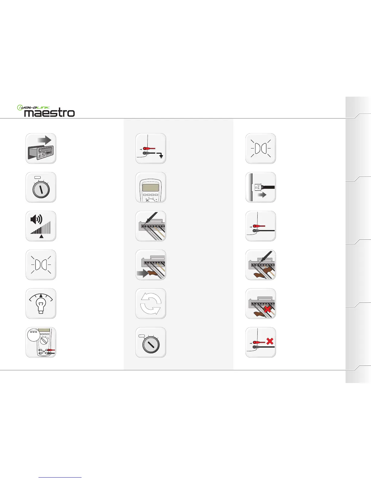
PROGRAMMINGEXTRAS PREPARATIONINSTALLATION
Pull out the radio.
Do not disconnect harnesses!
Turn key to ACC position
Turn the radio ON.
Set volume to medium.
Turn the parking lights OFF.
Turn the parking lights ON.
Set the dashboard illumination dimmer to a
medium lighting intensity.
Set DMM (Digital Multimeter) to DC volts.
Connect red probe at input terminal for
voltage and resistance.
Connect black probe at common (return)
terminal.
Apply RED DMM probe tip to 12V(+).
Apply BLACK DMM probe tip to Ground(-).
Continue to apply RED DMM probe tip to
12V(+).
Remove RED DMM probe tip from 12V(+).
Apply BLACK DMM probe tip to a first wire
of the radio.
Turn key to OFF position and remove key
from ignition switch.
When DMM displays an approximative
reading of 12V(+), apply a BROWN SWI F
label on the wire. (Voltage must be stable
and not fluctuate to the sound of music.)
Remove the BROWN SWI F label from all
wires that read approximately 12V(+).
Disconnect the radio harnesses.
Apply BLACK probe tip to each wire with a
BROWN SWI F label.
Look for wires that read approximately
12V(+).
DMM should display approximately 12V(+).
If DMM does not test 12V(+), repair the test
equipment before proceeding.
WWW.IDATALINK.COM/SUPPORT
Automotive Data Solutions Inc. © 2012
Radio Wiring (Identifying/Gathering information)
Repeat steps 09 and 10 until all radio wires
have been tested.
Maestro Install Guide / Vehicles not currently covered