PROGRAMMINGEXTRAS PREPARATIONINSTALLATION
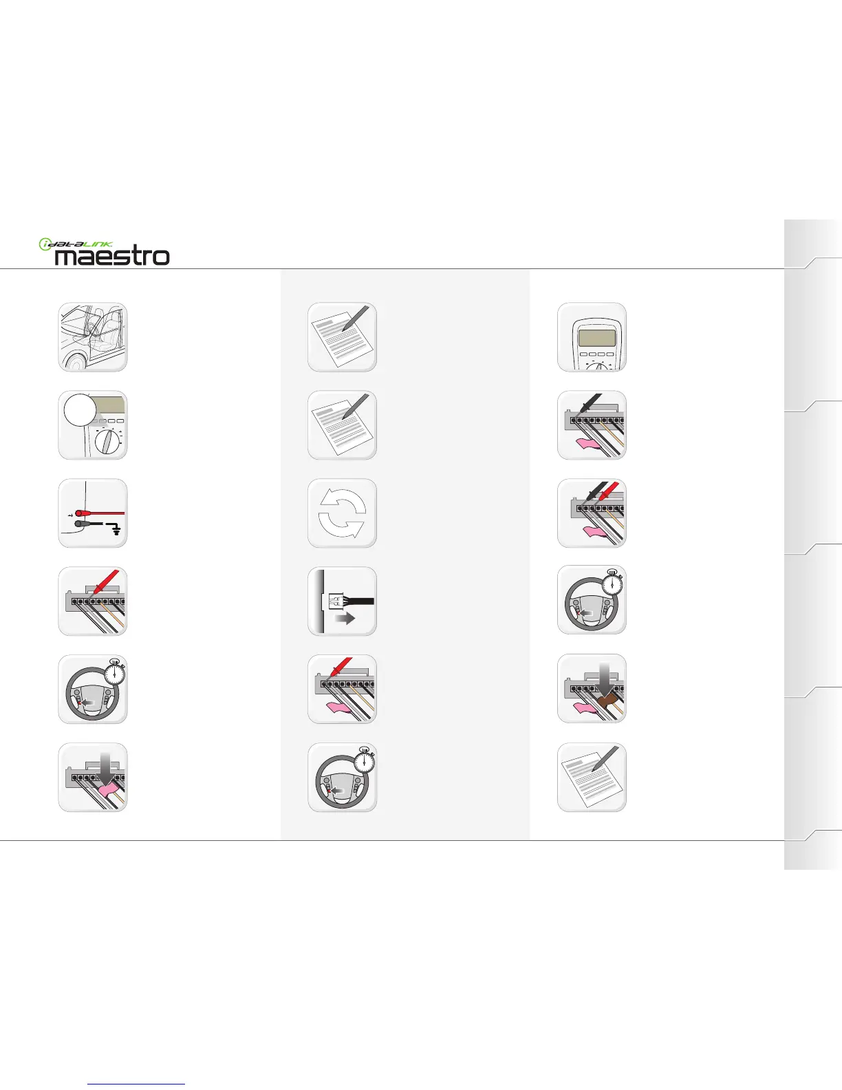
Disconnect the module.
Press and hold for 3 seconds each steering
wheel button linked to the wire, 1 at a time.
When releasing button, look for a change of
resistance on the DMM.
Apply BLACK DMM probe tip to a first wire
with a PINK SWI label.
Apply RED DMM probe tip to a first wire with
a PINK SWI label.
When DMM displays a change of resistance
apply a BROWN SWI F label on the wire.
Apply RED DMM probe tip to a first wire of
the radio.
If there is a change of resistance: Go to
step 30.
If there is NO change of resistance: Go to
next step.
Press and hold for 3 seconds, each
steering wheel button that is not already
linked, 1 at a time.
When releasing button, look for a change
of resistance on the DMM.
Press and hold for 3 seconds, each
steering wheel button linked to the wire, 1
at a time.
When releasing button, look for a change
of resistance on the DMM.
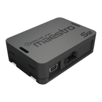
Locate external module (ex. Bluetooth or
navigation module).
Set DMM to OHMS.
Apply BLACK DMM probe tip to Ground(-).
Apply RED DMM probe tip to a first wire of
the external module connector.
External module Wiring (Identifying/Gathering information)
Repeat steps 04 through 08 until each
steering wheel button is linked to a signal
wire.
WWW.IDATALINK.COM/SUPPORT
Automotive Data Solutions Inc. © 2012Maestro Install Guide / Vehicles not currently covered
When DMM displays a change of resistance
apply a PINK SWI label on the wire.
Record in section A the color and location of
the signal wire.
(Wire with a PINK SWI label.)
Record in section B the color and location of
the feed wire.
(Wire with a BROWN SWI F label.)
Record in section C the names of steering
wheel buttons linked to the signal wire.
(Buttons that provided a change of
resistance when pressed and released).