88.88
Ω
DC
PROGRAMMINGEXTRAS PREPARATIONINSTALLATION
External module Wiring (Identifying/Gathering information)
WWW.IDATALINK.COM/SUPPORT
Automotive Data Solutions Inc. © 2012
Maestro Install Guide / Vehicles not currently covered
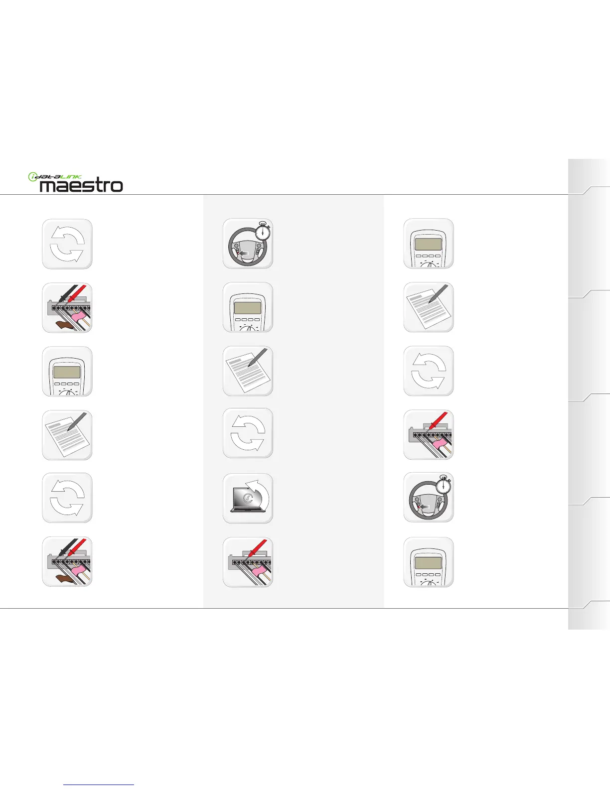
Repeat steps 30 through 32 for every
signal wire (with a PINK SWI tag.)
Repeat steps 14 through 18 for every
signal wire (with a PINK SWI tag.)
Apply RED DMM probe tip to first signal
wire (PINK label).
Apply BLACK DMM probe tip to Ground(-).
Measure resistance value between ground
and signal wire.
Record resistance at idle value in section
A.
One at a time, press and hold each
steering wheel button linked to that signal
wire.
Apply RED DMM probe tip to first signal
wire (PINK label).
Apply BLACK DMM probe tip to Ground(-).
Go to step 35 in Radio wiring
(Identifying/Gathering Information)
section.
For each button, measure resistance value.
(Wait for a stable reading.)
Measure resistance value between feed
wire and signal wire.
Record resistance at idle value in section A.
For each button, measure resistance value.
(Wait for a stable reading.)
For each button, record resistance value in
section C.
Apply RED DMM probe tip to first signal wire
(PINK label).
Apply BLACK DMM probe tip to linked feed
wire (BROWN label).
One at a time, press and hold each steering
wheel button linked to that signal wire.
Apply RED DMM probe tip to first signal wire
(PINK label).
Apply BLACK DMM probe tip to linked feed
wire (BROWN label).
Repeat steps 20 through 22 for each signal
wire.
Repeat steps 24 through 27 for each signal
wire.