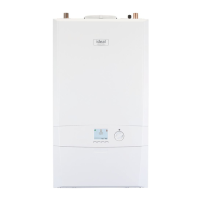
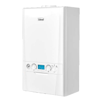
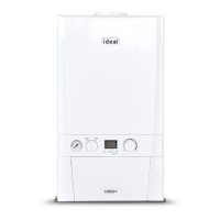
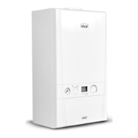
This document is a user guide for the Ideal Logic Heat2 H12, H15, H18, H24, and H30 boilers, which are heat-only appliances designed for central heating and hot water when connected to a separate hot water cylinder. The boilers feature a full sequence automatic spark ignition and fan-assisted combustion.
Function Description
The Logic Heat2 H boiler is a high-efficiency, condensing appliance that automatically adjusts its output to match the demand for heat, thereby reducing gas consumption. Due to its high efficiency, condensate is produced from the flue gases and is drained through a plastic waste pipe at the base of the boiler, which may result in a visible condensate 'plume' at the flue terminal. The appliance is designed to provide central heating and hot water, with the hot water temperature for the tap being set by the thermostat on the hot water cylinder.
Usage Features
- Starting the Boiler: To start the boiler, switch on the electricity and ensure all external controls (programmer, room thermostat, cylinder thermostat) are on. If "OFF" is displayed, press the Mode button until "ON" appears. Turn the Temperature control knob to 80°C. The boiler will then initiate its ignition sequence.
- Boiler Operation Modes:
- Winter/Summer Conditions: When domestic hot water and/or central heating are required, ensure "ON" is displayed. The boiler will then supply heat to the hot water cylinder and radiators.
- Boiler Off: To turn the boiler off (when neither domestic hot water nor central heating is required), ensure "OFF" is displayed.
- Water Temperature Control:
- No Outside Sensor Connected: The temperature of the water leaving the boiler for radiators or the hot water cylinder can be set between 30°C and 80°C by rotating the Temperature Control Knob.
- Outside Sensor Connected: If an outside sensor is connected, the hot water cylinder temperature is factory set to 80°C. The nominal central heating room temperature can be set between 10°C and 30°C by rotating the Temperature control knob. Rotating clockwise increases the temperature, while anti-clockwise rotation makes the system run more efficiently.
- Efficient Heating System Operation: To operate the boiler efficiently and use less gas, turn the central heating temperature knob lower. During colder periods, it may be necessary to increase the temperature setting to meet heating requirements. Reducing the room thermostat setting by 1°C can reduce gas consumption by up to 10%.
- Boiler Frost Protection: The boiler includes frost protection that operates in all modes, provided the power supply is always on. If the water in the boiler falls below 5°C, the frost protection will activate to prevent freezing within the boiler. This feature does not guarantee protection for all other parts of the system. If a system frost thermostat is installed, the boiler must be set in winter mode (without a cross through the radiator symbol) for system frost protection to run.
- Preventative Solutions for Cold Weather: During cold weather, set the central heating temperature knob to maximum (returning to the original setting after the cold spell). Place the heating on continuous and turn the room thermostat down to 15°C overnight or when unoccupied (returning to normal after the cold spell).
- Frozen Condensate Drain: The appliance is fitted with a siphonic condensate trap system to reduce the risk of freezing. If the condensate pipe freezes, it may cause a gurgling noise and lead to an "L0d" or "L02" fault code. To unblock, locate the frozen blockage (likely at exposed points, bends, elbows, or dips) and apply a hot water bottle, microwaveable heat pack, or warm damp cloth. Warm water can also be poured onto the pipe, but DO NOT use boiling water. Once unblocked, restart the appliance. If the issue persists, contact a Gas Safe Registered installer.
- Restarting the Boiler: If an "L" code is shown on the display, the boiler can be restarted by pressing the Restart button. If the boiler fails to light after five attempts, a fault message like "L02" will be displayed, and the Restart button should be pressed again. If it still fails, consult a Registered Gas Installer.
- User Control Display Codes: The user control display shows the boiler's status and flame presence.
- "OFF": Boiler Off Mode.
- "ON" (with flame symbol): Boiler On Mode, no Heat Demand.
- "52°C ON" (with flame symbol): Boiler is active for Central Heating.
- "FP ON": Boiler is active for boiler frost protection (operates if ambient temperature is below 5°C until 19°C is reached).
- "L 01" (or other number): Boiler is in Lockout for a specific error.
- "F 01" (or other number): Boiler has a fault for a specific error.
Maintenance Features
- Servicing: The frequency of servicing depends on installation conditions and usage, but it should be carried out at least annually by a Gas Safe Registered Engineer.
- Cleaning: For normal cleaning, dust with a dry cloth. For stubborn marks and stains, wipe with a damp cloth and finish with a dry cloth. DO NOT use abrasive cleaning materials.
- Minimum Clearances: Clearances of 165mm above, 100mm below, 2.5mm at the sides, and 450mm at the front of the boiler casing are required for servicing. The bottom clearance after installation can be reduced to 5mm with an easily removable panel, allowing the system pressure gauge to be visible and providing the 100mm clearance for servicing.
- Boiler Pump Self-Check: The boiler pump operates briefly as a self-check once every 24 hours, regardless of system demand.
- Gas Safety: All installation and maintenance work must be carried out by a Gas Safe Registered engineer. If a gas leak or fault is suspected, contact the National Gas Emergency Service immediately (0800 111 999). Ensure all naked flames are extinguished, electrical switches are not operated, and all windows and doors are opened.
- Electrical Supply: The appliance must be earthed, with a supply of 230 V ~ 50 Hz and a 3A fuse.
- Spare Parts: When replacing any part, use only spare parts that conform to the safety and performance specifications required by Ideal Heating. Do not use reconditioned or copy parts that have not been authorized by Ideal Heating.
- Benchmark Scheme: Ideal Heating is a member of the Benchmark scheme, which aims to improve installation, commissioning, and servicing standards for central heating systems. The Benchmark Service Interval Record must be completed after each service.