SignalTEK NT 156875 Iss 3
User Guide Page 52
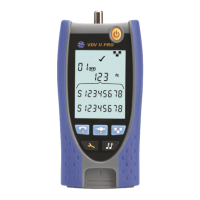
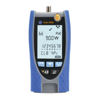
Connectors
(continued)
System Ports
Power
Used for - Battery charging
- Mains powering via adaptor
Connector type - 2.5mm pin power jack
Polarity - Centre pin positive
Voltage - 12v
Current - 2 amps
Location - Bottom of power module
Controls
ON/OFF
Push button
Used for - Power ON/OFF
Location - Front
Autotest
Push button
Used for - Instructing connected Near-End Unit to start its Autotest
Location - Front
Displays
LEDs
Charger LED
Used for - Indication of charging status…
Green - Battery is charging
Off (with charger connected) - Battery is charging
Green flashing - Battery is not charging
Color - Green
Location - Bottom of Power module
Power LED
Used for - Indication of battery and power status…
Green - Power ON. Buttery level sufficient for use
Red - Power ON. Battery charge level low but still operational.
Off - Power OFF
Color - Red / Green
Location - Front
RJ45 Link LED
Use - ON indicates link UP
Location - Adjacent to RJ45 socket, nearest top of tester
Color – Green
RJ45 Activity LED
Use - Flashing indicates link activity
Location - Adjacent to RJ45 socket, nearest bottom of tester
Color - Green
(continued)
 Loading...