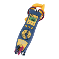
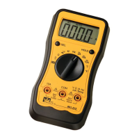
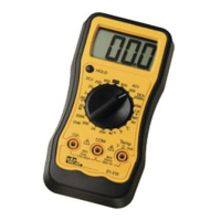
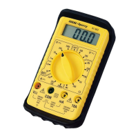
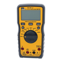
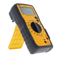
The IDEAL 700 Series 200 Amp Clamp Meters, models #61-702 and #61-704, are versatile electrical testing instruments designed for a range of measurements in various electrical applications.
Function Description:
These clamp meters are primarily used for measuring AC current without breaking the circuit, as well as AC/DC voltage, resistance, capacitance, and frequency. They also feature continuity and diode check functions. A key feature is the Non-Contact Voltage (NCV) detection, which allows users to detect AC voltage without direct contact. The #61-702 model includes a Hold button, while the #61-704 model adds a Backlight feature and True RMS Sensing for more accurate AC measurements, especially with non-sinusoidal waveforms.
Important Technical Specifications:
- Display: 3-1/2 digit LDC display.
- Polarity Indication: Automatic, negative indicated, positive implied.
- Overrange Indication: "OL".
- Low Battery Indication: Displayed when battery voltage drops below operating voltage.
- Auto Power Off: Approximately 60 minutes to conserve battery life.
- Temperature Coefficient: 0.1 x (specified accuracy) / °F, <64°F or >82°F.
- Power Requirements: 9V NEDA 1604 battery.
- Battery Life: 150 hours typical with alkaline, 75 hours typical with carbon zinc.
- Installation Category: IEC 1010-1, IEC1010-2-032, Cat III 1000V.
- AC Current Range: 200A with 0.1A resolution, Max Display 199.9, Accuracy ±(3%+5).
- Frequency response: 50Hz - 60Hz; ±(5%+5) 60Hz - 400Hz.
- True RMS Sensing: (61-704 only).
- DC Voltage Ranges:
- 2000mV: 1mV resolution, Max Display 1999, Accuracy ±(0.5%+1).
- 200V: 0.1V resolution, Max Display 199.9, Accuracy ±(0.5%+1).
- 1000V: 1V resolution, Max Display 1000, Accuracy ±(0.5%+1).
- AC Voltage Ranges:
- 2000mV: 1mV resolution, Max Display 1999, Accuracy ±(1.2%+3).
- 200V: 0.1V resolution, Max Display 199.9, Accuracy ±(1.2%+3).
- 750V: 1V resolution, Max Display 750, Accuracy ±(2%+5).
- Frequency response: 50Hz - 500Hz; ±(2%+5) 500Hz – 1KHz; 50Hz - 500Hz on 600V and 750V ranges.
- True RMS Sensing: (61-704 only).
- Resistance Ranges:
- 200Ω: 0.1Ω resolution, Max Display 200.0, Accuracy ±(1% +3).
- 200KΩ: 0.1KΩ resolution, Max Display 200.0, Accuracy ±(1% +3).
- Capacitance Range: 200MFD with 0.1MFD resolution, Max Display 199.9, Accuracy ±(3% +5).
- Continuity Check: Beeper sounds within 100mS if resistance is lower than 300 Ohms.
- Accuracy Specifications: Based on nominal operating temperature of 74°F ±8°, and a relative humidity less than 75%. Specified as ± (% of reading + number of least significant digits).
Usage Features:
- Non-Contact Voltage (NCV): Detects AC voltage by pressing the NCV button and placing the NCV tab near an AC voltage source. The NCV LED lights and a beeper sounds, with loudness indicating proximity to voltage. This feature can differentiate between hot and neutral wires in an outlet, with a louder beep on the hot side.
- Test Probe Holder: A single test probe holder simplifies voltage testing.
- Indicator Lights:
- HI-V (High Voltage): Red LED blinks and beeper sounds when voltage greater than 30V is detected in any VAC/VDC range. The meter also shakes, providing a tactile warning.
- NCV (Non-contact voltage): Indicates non-contact voltage detection.
- Continuity: Indicates continuity.
- CP (Clean Power): Green LED indicates clean 60Hz AC power. If off, the circuit has more than 5% (±2%) total harmonic distortion. Sensitivity: 20VAC on 200VAC range; 90V on 750VAC range.
- Hold Button (#61-702): Captures the displayed value during measurement. Press again or use the reset button to clear.
- NCV Button: Activates non-contact voltage testing.
- Backlight (#61-704): Illuminates the display for approximately 60 seconds before auto-off.
- Max Button: Captures the maximum reading during a measurement. Press again or use the reset button to clear.
- Rotary Switch: Used to select the appropriate function and range for measurements.
- COM Port and + Port: Standard input ports for test leads for VAC, VDC, Frequency, Resistance, Capacitance, Diode, and Continuity checks.
- Lead Storage: Silicone test leads are provided, designed to remain flexible in cold weather and withstand high temperatures. They can be wrapped around the meter for convenient storage.
- Range Selection: Users should choose a range just above the expected value. "OL" (overrange) indicates a need for a higher range, while fewer than three numbers suggest a lower range for better resolution.
- AC Current Measurement: Requires separating one wire from a bundle and placing it in the clamp jaws.
- Voltage Measurement: Connect test leads in parallel with the load or circuit.
- Frequency Measurement: Connect test leads in parallel with the load or circuit. The meter auto-ranges for 2k, 20k, or 40k ranges.
- Resistance Measurement: Requires turning off power to the circuit/device and discharging capacitors. Connect test leads to the device.
- Capacitance Measurement: Requires disconnecting the capacitor from power, shorting terminals to discharge, and disconnecting any resistors. Connect test leads to the capacitor.
- Diode Check: Measures forward voltage drops across diode and transistor junctions. Requires turning off power and discharging capacitors. A good silicone diode typically shows between 0.4V and 0.8V. "000" indicates a short circuit, and "OL" indicates non-conductive.
Maintenance Features:
- Battery Replacement: When the low battery indicator is displayed, the 9V NEDA 1604 battery must be replaced. This involves disconnecting leads, turning the meter off, and removing the battery cover.
- Cleaning: The exterior of the meter should be cleaned with a clean, dry cloth. Do not use liquid.
- Lead Inspection: Visually inspect test leads for damage before each use. Replace if insulation is damaged or leads appear suspect.
- General Safety: Users are warned against exceeding voltage ratings (750VAC or 1000VDC), performing resistance functions on circuits greater than 600V, or frequency/capacitance/continuity functions on circuits greater than 500V. The NCV function should be tested on a known live wire before use. Avoid use during electrical storms. Power to circuits should be turned off before taking resistance and capacitance measurements, and all capacitors fully discharged. The meter should be visually inspected for damage and its proper working order verified with a continuity check (reading from overload to zero).
- Repairs: Repairs or servicing not covered in the manual should only be performed by qualified personnel, and test leads should be removed before opening the cover to avoid electrical shock.
Warranty:
The tester is warranted to the original purchaser against defects in material and workmanship for two years from the date of purchase. IDEAL INDUSTRIES, INC. will, at its option, replace or repair the defective unit. The warranty does not cover defects from abuse, neglect, accident, unauthorized repair, alteration, or unreasonable use. Implied warranties are limited to those of merchantability and fitness for a particular purpose.