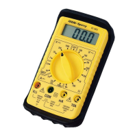
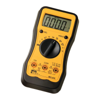
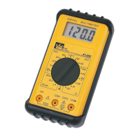
The IDEAL INDUSTRIES, INC. Model 61-603 is a technical manual for a 3½ Digit LCD display multimeter, designed for various electrical measurements and maintenance tasks. The device features a 2000-count display, with a maximum reading of 1999, and indicates overrange with a "1" as the most significant digit. It operates at a sampling rate of 3 times per second.
Technical Specifications:
- Display: 3½ Digit LCD, 2000 count.
- Overrange Indication: "1" (most significant digit).
- Sampling Rate: 3 times/second.
- Operating Environment:
- Temperature: 0°C to 40°C (32°F to 104°F).
- Relative Humidity: 80% for temperatures up to 31°C, decreasing linearly to 50% at 40°C.
- Storage Environment:
- Temperature: -20°C to 60°C (-4°F to 140°F).
- Relative Humidity: <80%.
- Power Source: 9V Battery (NEDA 1604).
- Battery Life: 150 hours typical (alkaline).
- Low Battery Indicator: A "+" symbol indicates low battery voltage.
- mA Protection Fuse: 500mA, 250V fast-acting fuse.
- Dimensions: 5.0" H x 2.8" W x 1.4" D (128mm H x 72mm W x 36mm D).
- Weight: Approximately 7.0 oz. or 200g (including battery).
Measurement Ranges and Accuracy:
- AC Voltage:
- Ranges: 200.0V, 500V.
- Accuracy: 1.0% ± 4 digits.
- DC Voltage:
- Ranges: 2.000V, 20.00V, 200.0V, 1000V.
- Accuracy: 0.5% ± 2 digits.
- AC Current: Not applicable (n/a).
- DC Current:
- Ranges: 2.000mA, 20.00mA, 200.0mA, 10.00A.
- Accuracy: 1.0% ± 1 digit (for 2.000mA, 20.00mA, 200.0mA), 2.0% ± 2 digits (for 10.00A).
- Resistance:
- Ranges: 200.0Ω, 2.000KΩ, 20.00KΩ, 200.0KΩ, 2.000MΩ.
- Accuracy: 1.2% ± 3 digits (for 200.0Ω), 1.0% ± 1 digit (for 2.000KΩ, 20.00KΩ, 200.0KΩ), 1.5% ± 2 digits (for 2.000MΩ).
- Diode Check: DCV 2V @ 1.0 mA ± 0.6 mA.
- AC Converter: Average responding, RMS calibrated to Sine Wave.
- Overload Protection:
- AC and DC Voltage: 1100 VDC or 500VAC RMS for no more than one minute.
- Resistance: 250VDC or AC RMS.
- 10A input: Un-fused.
- mA input: 500mA at 250V fast-acting fuse.
Usage Features:
The manual outlines essential safety precautions and operational guidelines. Users are warned against performing verification tests or calibration procedures without proper qualification to avoid shock or injury. The device contains static-sensitive parts, requiring standard handling practices.
- Safety Information: Emphasizes the use of proper fuses, operating with covers in place, avoiding electrical overloads, preventing electric shock by not connecting/disconnecting probes to live voltage sources, and refraining from operation in wet/damp conditions.
- Performance Verification: A procedure to ensure the meter is functioning correctly. This involves warming up a calibrator for 30 minutes, checking the battery voltage (must be at least 7.5V DC), and inputting specific values to verify readings against defined low and high limits for various functions (ACV, DCV, DCmA, Resistance). If the meter does not conform to these limits, calibration is required.
- Calibration: A recommended annual procedure.
- Preparation: Involves warming up the calibrator, disconnecting test leads, turning the range switch to "OFF," removing the bottom case cover, and ensuring the battery voltage is at least 7.5V DC.
- Procedure: For Volts DC Calibration, set the function/range to 2V DC, connect the calibrator to the VΩ and COM inputs, output 1.900V DC, and adjust R47 until the display reads 1.900V. This is the only adjustment required for the 61-603.
Maintenance Features:
- Battery Replacement:
- Disconnect test leads and turn off the meter.
- Slide off the back case battery cover.
- Remove the old 9V battery and unsnap its connector.
- Install a new 9V alkaline battery (NEDA #1604), ensuring not to pinch or bind battery leads.
- Slide the battery cover back until it snaps into place.
- Fuse Replacement:
- Disconnect test leads and turn the range switch to "OFF."
- Remove the screw holding the bottom case cover.
- Lift the battery end of the case bottom until it unsnaps from the top case.
- Remove the defective fuse and replace it with a 500mA, 250V Fast Acting fuse (IDEAL #F-7 Type is recommended).
- Replace the bottom cover, ensuring it is secured by the internal snaps and then replace the screw.
The manual also includes a diagram of the 61-603 main printed circuit board for reference during maintenance and calibration.