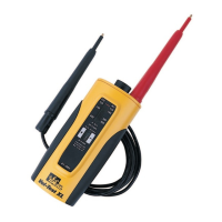
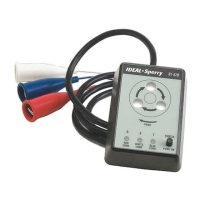
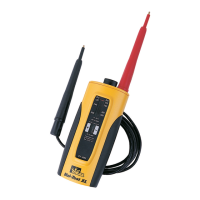
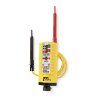
Cautions
• To avoid the risk of electrical shock, discon-
nect test leads before removing the battery
pack. Do not operate unit with the battery
pack removed.
• Do not use on over 600 volts. This instrument
is for intermittent service only. The duty cycle
on:off ratio is 1:7 for 240 volts or less, and
1:40 for 240 volts or greater. Fifteen seconds
is the maximum “On” time.
• All indications are relative. For determining
the nominal line voltage only.
• Do not use unit with battery packs removed.
Unit may be used for “checking for voltage”
without batteries; however, the battery packs
must be in place for safe operation.
• Always remove right angle plug on lead set
prior to removing battery packs.
Note: If LEDon the left does not come “On”
when it should, check the battery pack on the
left. If LED on the right does not come “On”
when it should, check the battery pack on the
right. Pack may not be fully seated, batteries
may not be oriented correctly or batteries are
bad.
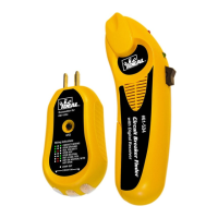
Assembly Instructions
• Remove lead set plug. Remove the two bat-
tery packs adjacent to the lead set, plug
opening. Use screwdriver as a lever, insert-
ing tip in slot at edge of cap and under the
battery pack head. A light force will pop the
pack loose for easy hand removal.
• Insert four 1-1/2 volt watch/calculator batter-
ies (two per each pack), putting negative ter-
minal down as indicated on the side of the
battery pack. Use Union Carbide Corp.
Type A76VP, Eveready No. 357 or IDEALNo.
61-201.
• Orient the battery packs and snap into tester.
Be sure the packs are fully seated.
• Press right angle plug on lead set into the
bottom of the tester. (Place plug on a bench
or solid object and push tester into plug.)
This is a tight fit to keep moisture away from
pins and to prevent accidental plug
release. Be sure the plug is fully
seated.
• Retract “safety shield” on prod tips
and lock by rotating. Place one
prod into the “probing position” by
putting the handle into the prod
storage well. Bring the two
exposed tips into contact with each
other; the continuity LED (LED to
the left) should now be “On.” This
assures batteries on the left side
are good and your “lead set” is in
good working condition. Always
perform this test before using
tester.
• Test a known live AC circuit such as
120 volts. Both LEDs should be
“On”; the neon should have “fired”
if voltage is over 80 and the sole-
noid coil indicator should be acti-
vated. Tester is now operational.
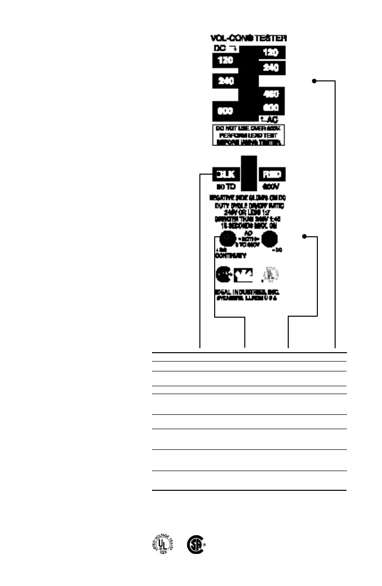
Neon Bulb Left LED Right LED Scale
Continuity Off On Off No movement.
OpenCircuit
No Voltage Off Off Off No movement.
6-65 AC Off On On No movement.
6-90 DC Off On if black prod is On if red prod is No movement.
on negative, off if on negative, off if
it is on positive. prod is reversed.
65-110 AC On On On Little or no
movement.
90-110 DC On On if black prod is On if red prod is Little or no
on negative, off if on negative off if movement.
it is on positive. prod is reversed.
110-600AC On On On
Scale indicates
relative
magnitude.
110-600 DC On On if black prod is On if red prod is
Scale indicates
on negative, off if on negative, off if
relative voltage.
it is on positive. prod is reversed.
Warranty limited solely to repair or replacement; no warranty of merchantability, fitness for a particular purpose or consequential
damages.
ND 2838-1 Vol-Con Test Inst sh 11/29/00 11:12 AM Page 2
 Loading...