Do you have a question about the IDEATEC DLC4000 and is the answer not in the manual?
Details essential safety instructions and precautions for installing automobile electronics to prevent injury or damage.
Provides a guide for correctly dimensioning electrical wires based on current and length to prevent fire hazards.
Describes the features and capabilities of the DLC4000 and DLC8000 control systems, including outputs and inputs.
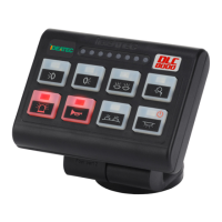
Illustrates the physical arrangement and connection points of the DLC4000/DLC8000 console and module.
Identifies key components of the DLC4000/DLC8000 system, including console and mounting kits.
Details specifications and options for the bus cable connecting the console and module, with length limitations.
Lists the part numbers and descriptions for the DLC4000 and DLC8000 power modules.
Describes the set of 88 pictograms provided for use with the console keys.
Provides step-by-step instructions for installing the console onto the dashboard.
Detailed steps for positioning, fixing, and attaching the console, including tool references.
Instructions for mounting the power module, emphasizing flat surface, ventilation, and protection against humidity.
Provides guidance on controlling template scale and presents the console mounting foot drilling template.
Shows the dimensions for the DLC4000/DLC8000 power module for drilling purposes.
Details the technical specifications for the console, including voltage, temperature, weight, and dimensions.
Lists technical specifications for the power module, covering voltage, temperature, outputs, current, and weight.
Presents the overall wiring diagram for connecting the DLC4000/DLC8000 module and console.
Explains the importance of proper terminal crimping for reliable connections.
Illustrates the specific wiring connections for the DLC4000 power module.
Illustrates the specific wiring connections for the DLC8000 power module.
Details the predefined functions assigned to each key on the console by default.
Explains how to insert pictograms into console keys and describes light/sound codes.
Describes the console design, pictogram insertion, and the meaning of different light and sound codes.
Explains the behavior of console keys, including sleep mode and permanent lit states.
Provides recommendations for pictogram placement and lists conditions required for configuration.
Details how to select and place pictograms on console keys for proper application.
Specifies the power and connection requirements to enter the configuration mode.
Explains the two modes for configuration and how to initiate them via key presses.
Describes how key flashes indicate selected options and how to change them.
Instructs on how to save the configured settings by pressing specific key combinations.
Details configurations for Key B1 and positive input 3, including default and alternate functions.
Explains configurations for Key B1 and positive input 3 related to siren and blue light functions.
Details configurations for Key B2 and negative input 2, including slave mode and handbrake conditions.
Explains further configurations for Key B2 and negative input 2, focusing on siren and handbrake interactions.
Details configurations for Key B3 and negative input 2, including grill light and handbrake conditions.
Details configurations for Key B4 and negative input 2, including markup function and handbrake conditions.
Explains configurations for Key B5, including scene activation and group functions.
Details configurations for Key B6, including scene activation and group functions.
Explains configurations for Key B7, including group functions and arrowstick control.
Details configurations for Key B8, including group functions and arrowstick control.
Explains how keys B5-B8 function in group 1, where only one key can be active at a time.
Details how keys B5-B8 function in group 2, where only one key can be active at a time.
Explains how keys B5 and B6 act as scene activators and their interaction with other keys.
Details automatic standby configurations for the DLC4000/DLC8000 system.
Explains automatic standby settings based on key activity and positive input 1 status.
Describes how key B4 behaves (flashing or not) when the system is in standby mode.
Details conditions for directional lightbar configuration using negative input 2 (handbrake) for keys B5-B8.
Explains the simulation for directional lightbar function based on the state of keys B5, B6, B7, and B8.
Informs about the availability of all IDEATEC user guides on a single CD-ROM.
Details the two-year warranty provided by IDEATEC S.A. for the product.
| Brand | IDEATEC |
|---|---|
| Model | DLC4000 |
| Category | Control Systems |
| Language | English |