IDEATEC S.A. - Z.I. de Noville-les-Bois - rue Léopold Génicot 19A - 5380 Fernelmont, Belgium - Tel: +32(0)81 42 00 10 - Fax: +32(0)81 57 91 70 - E-mail: info@ideatec.be
User’s guide DLC4000/DLC8000 - Doc. V2.1 - Firmware V3.1
Page 5
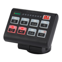
5.1. Console
&
ÜYou can configure the keys on
the keypad using the set of 88
pictograms provided.
ÜTo ensure good adherence of
the pictogram to the cavity on
each key, avoid touching the
adhesive part of the
pictograms and the key
cavities with your fingers.
5.
The safety of future users of this product depends on your installation. Therefore, it is critical that
you read, understand, and follow all instructions contained in this installation guide.
Ü Preassemble the console without blocking the 2 hexagonal head screws.
Ü Choose the best place to install the console on the dashboard.
Ü Locate and note the 6 fixation holes at the base of the foot.
Ü Fix the base and position of the console perfectly.
Ü Block the 2 hexagonal head screws.
Ü Attach the cover to the back of the foot with the screw provided.
Ü Place the small black cap on the head of the screw on the back.
ÜIf the angle chosen to install the console allows it, the RJ-45 cable can be connected.
If necessary, loosen the screw to access the back of the console more easily.
Use only screws, nuts, and washers provided by the manufacturers.
Using other longer screws in the back of the console may seriously damage its internal parts.
The manufacturer cannot assure any warranties or accept liability if other fixing elements or screw,
nuts, and washers are used to install the console.
iTool reference: hex head key n°6
iDrilling template on page 7
Console and module installation