4: OPERATION BASICS
4-4 « FC4A MICROSMART USER’S MANUAL »
Start/Stop Operation Using the Power Supply
The MicroSmart can be started and stopped by turning power on and off.
1. Power up the MicroSmart to start operation. See page 4-1.
2. If the MicroSmart does not start, check that start control special internal relay M8000 is on using WindLDR. If M8000
is off, turn it on. See page 4-3.
3. Turn power on and off to start and stop operation.
Note: If M8000 is off, the MicroSmart does not start operation when power is turned on. To start operation, turn power on,
and turn M8000 on by clicking the Start button in
WindLDR.
The response time of the MicroSmart at powerup depends on such factors as the contents of the user program, data link
usage, and system setup. The table below shows an approximate time delay before starting operation after powerup.
Response time when no data link is used:
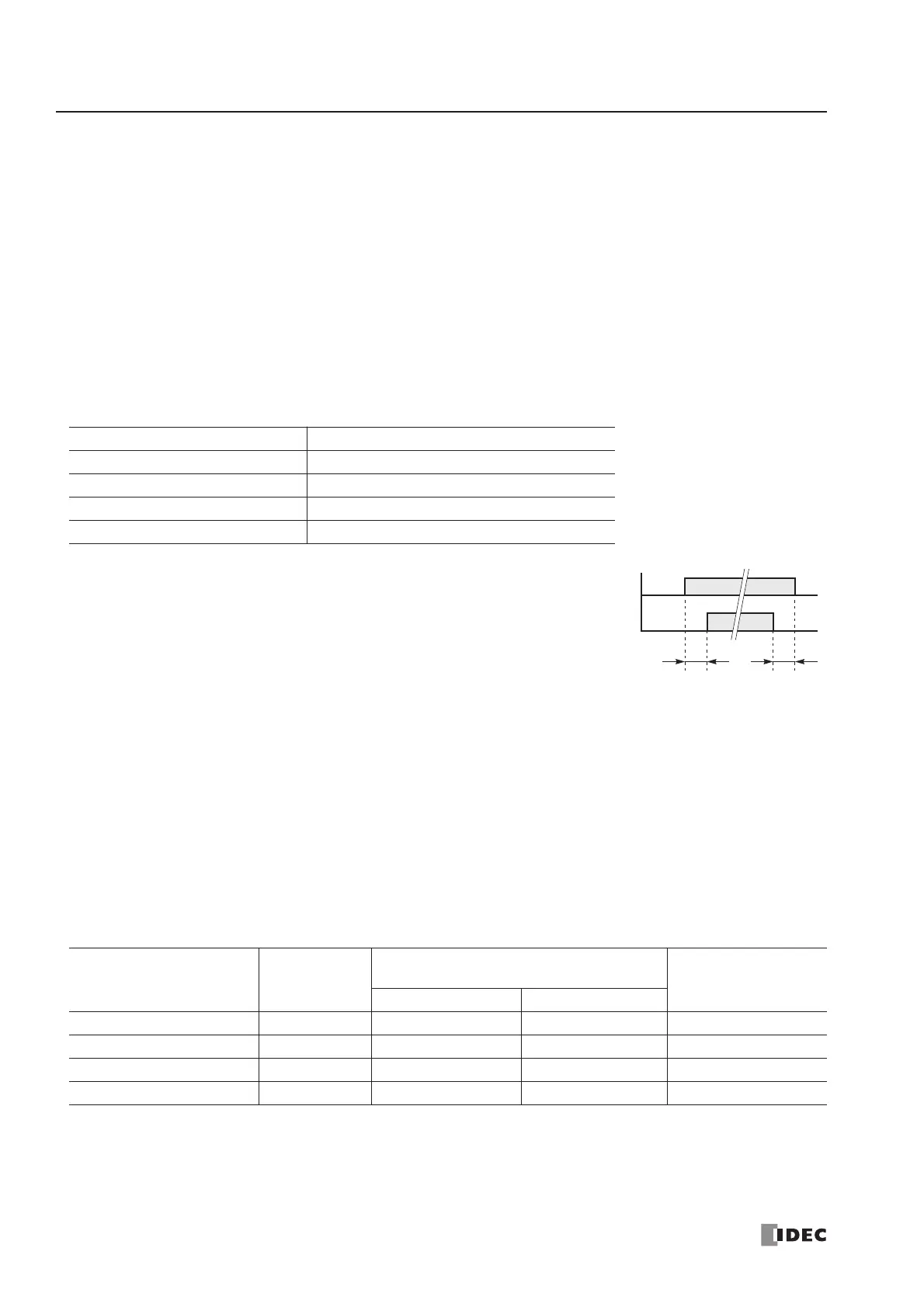
Order of Powerup and Powerdown
To ensure I/O data transfer, power up the I/O modules first,
followed by the CPU module, or power up the CPU and I/O
modules at the same time. When shutting down the system,
power down the CPU first, followed by I/O modules, or
power down the CPU and I/O modules at the same time.
Start/Stop Operation Using Stop Input and Reset Input
Any input terminal available on the CPU module can be designated as a stop or reset input using the Function Area Set-
tings. The procedure for selecting stop and reset inputs is described on page 5-2.
Note: When using a stop and/or reset input to start and stop operation, make sure that start control special internal relay
M8000 is on. If M8000 is off, the CPU does not start operation when the stop or reset input is turned off. M8000 is not
turned on or off when the stop and/or reset input is turned on or off.
When a stop or reset input is turned on during program operation, the CPU stops operation, the RUN LED is turned off,
and all outputs are turned off.
The reset input has priority over the stop input.
System Statuses at Stop, Reset, and Restart
The system statuses during running, stop, reset, and restart after stopping are listed below:
Note: Expansion data registers and AS-Interface operands are available on slim type CPU modules FC4A-D20RK1, FC4A-
D20RS1, FC4A-D40K3, and FC4A-D40S3. All expansion data registers are keep types. AS-Interface operands (M1300-
M1977 and D1700-D1999) remain unchanged when the reset input is turned on.
Program Size After powerup, the CPU starts operation in
4,800 bytes (800 steps) Approx. 0.5 second
15,000 bytes (2,500 steps) Approx. 1.2 seconds
27,000 bytes (4,500 steps) Approx. 2 seconds
64,500 bytes (10,750 steps) Approx. 5 seconds
Mode Output
Internal Relay, Shift Register, Counter,
Data Register, Expansion Data Register
Timer Current Value
Keep Type Clear Type
Run Operating Operating Operating Operating
Stop (Stop input ON) OFF Unchanged Unchanged Unchanged
Reset (Reset input ON) OFF OFF/Reset to zero OFF/Reset to zero Reset to zero
Restart Unchanged Unchanged OFF/Reset to zero Reset to preset