24: ANALOG I/O CONTROL
24-8 « FC4A MICROSMART USER’S MANUAL »
Data Register Allocation Numbers for Analog I/O Modules
Analog I/O modules are numbered from 1 through 7, in the order of increasing distance from the CPU module. Data regis-
ters are allocated to each analog I/O module depending on the analog I/O module number. END refresh type analog I/O
modules and ladder refresh type analog I/O modules have different data register allocation.
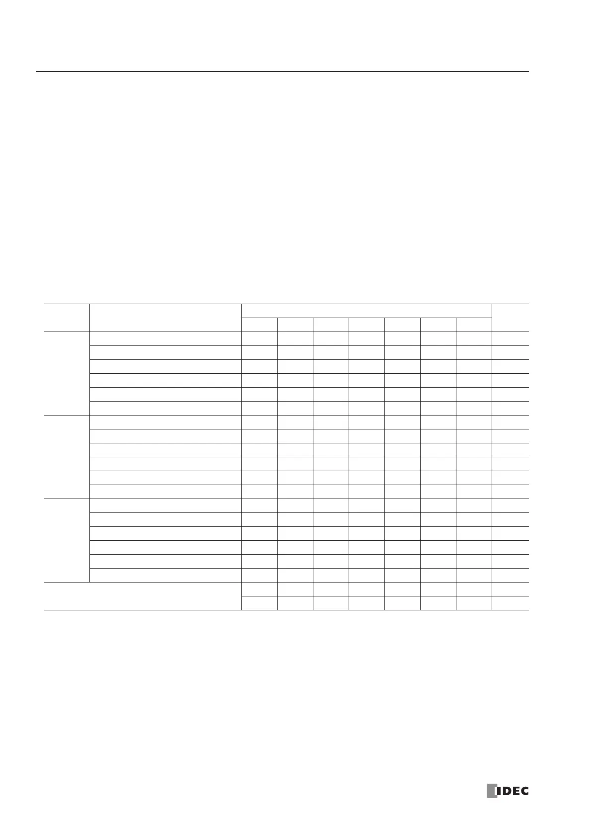
END Refresh Type Analog I/O Modules
Each END refresh type analog I/O module is automatically allocated 20 data registers to store parameters for controlling
analog I/O operation, starting with D760 through D779 for analog I/O module No. 1, up to D880 through D899 for analog
I/O module No. 7. When a maximum of seven analog I/O modules are not used, data registers allocated to the unused ana-
log I/O module numbers can be used as ordinary data registers.
When a maximum of seven END refresh type analog I/O modules are mounted, data registers D760 through D899 are
allocated to analog modules 1 through 7 as shown below. The ANST macro is used to program data registers for the analog
I/O module configuration. The CPU module checks the analog I/O configuration only once when the CPU starts to run. If
you have changed the parameter while the CPU is running, stop and restart the CPU to enable the new parameter.
The END refresh type analog I/O module number starts with 1 next to the CPU module up to a maximum of 7.
The run-time program download and test program download cannot be used to change analog I/O parameters.
Note: Data registers allocated to the unused analog I/O module numbers can be used as ordinary data registers.
Channel Function
END Refresh Type Analog I/O Module No.
R/W
1234567
Analog
Input
Ch 0
Analog input data D760 D780 D800 D820 D840 D860 D880 R
Analog input operating status D761 D781 D801 D821 D841 D861 D881 R
Analog input signal type D762 D782 D802 D822 D842 D862 D882 R/W
Analog input data type D763 D783 D803 D823 D843 D863 D883 R/W
Analog input data minimum value D764 D784 D804 D824 D844 D864 D884 R/W
Analog input data maximum value D765 D785 D805 D825 D845 D865 D885 R/W
Analog
Input
Ch 1
Analog input data D766 D786 D806 D826 D846 D866 D886 R
Analog input operating status D767 D787 D807 D827 D847 D867 D887 R
Analog input signal type D768 D788 D808 D828 D848 D868 D888 R/W
Analog input data type D769 D789 D809 D829 D849 D869 D889 R/W
Analog input data minimum value D770 D790 D810 D830 D850 D870 D890 R/W
Analog input data maximum value D771 D791 D811 D831 D851 D871 D891 R/W
Analog
Output
Analog output data D772 D792 D812 D832 D852 D872 D892 R/W
Analog output operating status D773 D793 D813 D833 D853 D873 D893 R
Analog output signal type D774 D794 D814 D834 D854 D874 D894 R/W
Analog output data type D775 D795 D815 D835 D855 D875 D895 R/W
Analog output data minimum value D776 D796 D816 D836 D856 D876 D896 R/W
Analog output data maximum value D777 D797 D817 D837 D857 D877 D897 R/W
– Reserved –
D778 D798 D818 D838 D858 D878 D898 R/W
D779 D799 D819 D839 D859 D879 D899 R/W